Integrated energy systems (IESs) are a method of aggregating and coordinating energy consumption management programs, storage, and resources1. Renewable energy sources, which are environmentally favorable, are typically implemented in an IES to mitigate emissions. These resources are available in a variety of forms, including tidal units (TU), photovoltaic (PV), wind systems (WS), and bio-waste systems (BS)2. Their generation capacity is unpredictable and fluctuates2. Consequently, the utilization of storage devices in IES is regarded as a sustainable energy source3. Storage devices can be implemented to optimize energy management in IES, in addition to compensating for the power fluctuations of renewable sources. Various varieties of storage devices exist. One such variety is hydrogen storage, which is equipped with hydrogen-to-power (H2P) and power-to-hydrogen (P2H) technologies. In addition to its capacity to store electrical energy, this storage system can also be utilized to supply the hydrogen burden4. Therefore, it is anticipated that this storage device will be of substantial utility in the IES. A role in energy transfer and storage can be played by IES with optimal operation5. Therefore, the economic and technical objectives of the distribution system operator (DSO) are improved by their presence in the power system5. These conditions are contingent upon the optimal energy management of IESs and their optimal planning (sitting and sizing) within the distribution system. Consequently, the technical conditions of the network can be improved by optimizing the planning and operation of renewable IESs in the distribution network using P2H and H2P technologies. This depends on the extraction of an acceptable optimization model.
Literature review
The topic of IESs in the distribution system has been the subject of numerous publications and studies, with a particular emphasis on operation and planning. A two-stage optimization method for a coupled capacity planning and operation problem, which is embedded within the economical operation of the regional IES, is presented in6. The first optimization stage of the proposed model is a regional IES planner that aims to reduce the energy and environmental costs of the system. The second stage is an operation problem that is primarily responsible for achieving the optimal operation scheme of the system. By co-optimizing the capacity configuration and power output of individual energy supply modules, the regional IES planner optimizes the installed capacity of renewable energy sources and reduces environmental costs, thereby pursuing the best interests of the region. To reduce the costs of IES operation and facilitate flexible and robust uncertainty planning, the hybrid robust-interval optimization framework was proposed in7. In order to account for the uncertainties associated with renewable energy generation output and demand response, the framework incorporated robust optimization and interval analysis. A constrained multi-objective transition algorithm was devised to solve the problem of modeling IES planning as a deterministic bi-objective optimization problem with investment operation cost and robustness as the optimization objectives. The industrial park-IES with hydrogen energy industry chain is proposed in8. Hydrogen production, transportation, and storage technologies are implemented in this system. Initially, a novel long-term hydrogen storage model that takes into account various time stages is introduced. Subsequently, hydrogen compressor models that account for various pressure ratios are implemented. A new strategy for reducing reliability costs is proposed in9in order to attain the lowest total cost. In this context, the vehicle-to-grid instrument is employed to decrease the overall system cost. The energy management model for the micro-grid in the grid-connected mode that has been presented accounts for the fluctuations in the output power of the wind turbine and photovoltaic systems, as well as the charging and discharging of plug-in electric vehicles. The modified fluid search optimization algorithm is used in this study to optimize the micro-grid operation problem. This algorithm is both innovative and effective. A grid-connected IES is proposed in10, which considers the complementarity of geothermal energy and solar energy and incorporates heat storage. A study is conducted on the multi-objective optimization problem of IES for the coupling mode of electric energy, heat energy, and cold energy. A multi-objective optimization model was developed with the objective of integrating the cost of operation, the cost of exergic efficacy, and the cost of pollution gas emission penalty by utilizing a multi-functional park as the research object.
An optimal scheduling model is proposed in11that encompasses the demand response of cooling, heating, and electricity consumption, as well as a ladder-type carbon trading mechanism. This model is based on Combined Cooling, Heat and Power system and a carbon capture device. Initially, a multi-energy and multi-type demand response model is developed, which is founded on the time-of-use electricity price and incentive mechanism. User satisfaction is employed to assess the model. Next, a carbon trading model for the integrated energy system is developed by taking into account the system’s actual carbon emissions and the ladder-type carbon trading mechanism. Ultimately, an optimal scheduling model that takes into account both low-carbon and economy is constructed by combining the operation constraints of multi-energy flow of integrated energy system with the objective function of the minimum sum of energy purchase cost, maintenance cost, carbon emission cost, and compensation cost. This transforms the problem into a mixed integer linear problem. Ref12. innovatively suggests an integrated energy system operation method that effectively reduces total operating costs and carbon emissions by enabling electric and heating loads to collaborate in demand response. Initially, the synergistic mechanism of electric and heating loads is examined, and a demand response strategy for electric and heating loads is suggested. Secondly, the electric load and thermal load demand response models are constructed based on the sensitivity of the electric load to the same electricity price and the flexibility of the thermal load, respectively. In13, a Stackelberg game theory-based operation strategy for a community IES is proposed, which considers the characteristics of supply and demand. The energy management of a smart distribution network, which includes an integrated energy system of hydrogen storage and renewable sources, is detailed in Ref14.. The objective is to evaluate the distribution system operator’s economic, operational, flexibility, and reliability objectives. The objective function is designed to reduce the costs of operation, reliability, energy losses, and network flexibility. The alternating current (AC) optimal power flow equations, network reliability limitations, and integrated energy system model all constrain the scheme. A cooperative operation method for multi-IESs is proposed in15to address the challenges encountered by an IES during independent operation, such as high operating costs and significant uncertainties in electricity prices and source-load. This method is based on a three-level Nash three-stage robust optimization. The rural comprehensive energy park distribution robust scheduling model for water-containing product breeding conservatories is proposed in16. Initially, a greenhouse model for aquaculture is developed using the principle of thermal diffusion. Subsequently, a rural integrated energy system model is developed by taking into account energy production, consumption, and storage. Reference17builds the flexible regulation models of thermal and electrical loads and introduces them to the structure expansion planning of IES. A two-stage stochastic probability optimization method integrating the uncertain operation of introducing flexible loads is then proposed to balance the additional costs of device integration and the benefits of performance promotion. Ref18. presents the unavailable operating region problem of the traditional IES and its flexibility improvement mechanism of integrating with the gas boiler, electric boiler, power-to-gas, electrical energy storage and thermal energy storage. Table 1 contains a summary of the pertinent research.
Research gaps
The following is a summary of the study openings in the field of IESs operation and planning in the power system, as indicated in Table 1:
The optimal operation of IESs in the distribution system is the sole factor considered in the majority of studies, such as9,10,11,12,13,14,15,1618. Nevertheless, the optimal placement and sizing of IESs can have a positive effect on the power system in addition to the operation of IESs, in order to enhance the economic and technical indices. However, the planning of IESs has been examined in conjunction with their operation in a limited number of references, including6,7,817. However, these works only examine the sizing model and do not take into account the placement model of IES.
Electrical energy management in IES has been the sole focus of the majority of research. However, at consumption locations, a variety of energies, including electricity, heat, and gas, are consumed. For instance, it is anticipated that a substantial number of electric vehicles powered by fuel cells will be implemented in the future in order to mitigate environmental concerns and advance technologies. Hydrogen is required for these vehicles. Consequently, it is anticipated that hydrogen consumption at consumption points will require management in addition to electric energy management. However, there is a dearth of research in the field of IESs, as evidenced by9.
The majority of research in the field of operation and planning of IESs has not taken into account the presence of P2H and H2P technologies. P2H is employed to generate hydrogen through the utilization of renewable energy sources. In other terms, P2H can be used as an electrolyzer (EL) to convert renewable electrical energy into hydrogen on the way to a renewable source. Hydrogen is utilized to generate electrical energy, which is denoted as H2P. It is analogous to a fuel cell (FC) that receives electrical energy and generates electrical energy at its output. Hydrogen storage is the term used to describe the combination of a hydrogen tank (HT) and P2H and H2P. This storage device operates at an acceptable level of efficacy. It can be constructed in large capacities and has a lengthy useful life. However, it is important to acknowledge that the battery is utilized as a storage device in the majority of the studies. The battery’s access to big capacities is difficult and expensive, and its construction is costly, despite its high power density and efficiency. Nevertheless, hydrogen storage can be implemented to mitigate these constraints. Furthermore, hydrogen charges may be supplied by the hydrogen storage. Previous investigations have seldom addressed this matter.
Renewable resources have been considered in order to achieve favorable environmental conditions and reduce operational costs in the power system. Nevertheless, wind and solar renewable sources have been implemented in the majority of studies, including6,7,8,9,10,11,12,13,15,16,17,18. Additionally, the bio-waste system (BS) is a renewable energy source that converts environmental refuse into electrical energy at its output. Nevertheless, the positive impact of BS operation on a variety of technical, economic, and environmental indicators has been assessed in a limited number of references, including14 which pertain to the IES operation.
The planning and operation of the IES are subject to a variety of uncertainties, including the load, renewable resources, and distribution network. Most research has employed scenario-based stochastic optimization (SBSO) to address the aforementioned uncertainties. In order to achieve a dependable solution, this approach necessitates a substantial number of scenarios. This problem results in a decrease in computation time due to the increased volume of the problem. However, minimal computing time is of particular significance in the context of power system operation issues. Some works, such as7,13,15,16,17,18, employed robust optimization to model uncertainties in order to address this issue. However, the worst-case scenarios of uncertainty parameters are the only scenario considered in this optimization. Although this issue is effective in reducing computing time, the worst-case scenario results in a high planning cost for IES. Despite the possibility that the worst-case scenario may occur with a poor degree of certainty. Thus, stochastic optimization techniques that employ the lowest scenario are required to account for these instances. The discipline of IES optimization has given less consideration to this issue.
Contributions
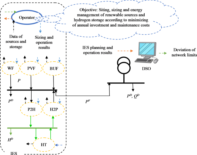
The proposed research gaps are addressed and resolved by the sitting and sizing of renewable IESs in the active distribution network (ADN) using P2H and H2P technologies, as illustrated in Fig. 1. The aforementioned IES takes into account the presence of BSs and manages electric and hydrogen energy. The optimization form is used to convey the proposed design. The total annual cost of construction and maintenance of renewable resources, P2H, H2P, and HT is minimized at the objective function. The operation and planning model of renewable resources, including wind farms (WF), photovoltaic farms (PVF), and bio-waste unit farms (BUF), as well as the operation and planning limitations of P2H, H2P, and HT, active power balance in IES, and AC optimal power flow model of ADN, are all constraints. The electrolyzer/fuel cell is included in the P2H/H2P in this article. Hydrogen is produced by the electrolyzer through the conversion of electrical energy. A portion of the hydrogen generated is utilized to fuel the hydrogen load, while the remaining portion is stored in HT. Additionally, hydrogen is supplied by HT to the fuel cell, which generates electricity at its output. The function of hydrogen storage (HS) is, of course, equivalent to the combination of H2P, P2H, and HT functions in this article. Renewable resources and the quantity of demand are uncertain in the proposed design. The final research gap is addressed by employing the stochastic optimization-based Unscented Transformation (UT) method to characterize this uncertainty and achieve a safe optimal solution. Lastly, the objectives and innovations of the present investigation are as follows:
The installation, sizing, and control of renewable IESs that are equipped with P2H and H2P technologies in the ADN.
Concurrent optimization of energy usage for both electricity and hydrogen customers in renewable IESs that are equipped with hydrogen storage.
Assessing the influence of the optimal performance of BSs, P2Hs, and H2Ps in IES on the technical condition of the distribution system.
Employing the UT approach to model uncertainty in load and renewable sources, aiming to provide a dependable solution within a short computation time.
Finally, the general contribution of this scheme is “Economic placement, sizing and energy management of renewable IES with hydrogen storage in the active distribution network according to the improvement of the operation goals of the distribution system operator based on UT approach-based stochastic optimization”.
In Sect. 2, we will discuss the planning and operation of IESs in ADN. Section 3 provides a description of the uncertainty modeling using the UT approach. Section 4 presents the quantitative results obtained from the analysis of specific instances. Ultimately, Sect. 5 concludes the paper.
Optimal placement and sizing of grid-connected renewable IESs.
Sitting and sizing of networked HS-based renewable IESs
In this article, it is assumed that the distribution network has an intelligent platform. Therefore, the term of the active distribution network was used in this article. In this network, it is expected that there is two-way coordination between the IES operator and the DSO based on Fig. 1. The IES operator is aware of the state or technical limitations of the network, therefore it determines the optimal location for itself in the network and then obtains the optimal size for resources and storage devices according to the network limitations. In the discussion of IES energy management, the IES operator is in bidirectional coordination with the renewable sources and hydrogen storage according to Fig. 1. It receives the data of these elements, and according to the network constraints announced to it by the DSO, it obtains the optimal power scheduling of the resources and storage devices and informs them. In other words, in order to implement the proposed plan on the distribution network in the real environment, it is necessary to have an intelligent platform in the network and IES.
This section presents the planning of IES, which involves the incorporation of P2H and H2P technologies in ADN. It reduces the cost of planning for IESs by considering the constraints of resources, storage devices, and the AC optimum power flow of ADN. Below is the mathematical statement of the problem:
$$\hbox{min} \,\,\,\,\,\,AIMC=\sum\limits_{n} {\left( \begin{gathered} N_{n}^{{WS}}I{C^{WS}}+N_{n}^{{PV}}I{C^{PV}}+N_{n}^{{BS}}I{C^{BS}}+N_{n}^{{P2H}}I{C^{P2H}}+N_{n}^{{H2P}}I{C^{H2P}}+N_{n}^{{HT}}I{C^{HT}}+ \hfill \\ N_{n}^{{WS}}M{C^{WS}}+N_{n}^{{PV}}M{C^{PV}}+N_{n}^{{BS}}M{C^{BS}}+N_{n}^{{P2H}}M{C^{P2H}}+N_{n}^{{H2P}}M{C^{H2P}}+N_{n}^{{HT}}M{C^{HT}} \hfill \\ \end{gathered} \right)}$$
(1)
Subject to:
$$P_{{n,h,s}}^{{WF}}=\,N_{n}^{{WS}}\bar {P}_{n}^{{WS}}\phi _{{n,h,s}}^{{WS}}\,\,\,\,\,\,\,\,\,\,\,\,\forall n,h,s$$
(2)
$$P_{{n,h,s}}^{{PVF}}=\,N_{n}^{{PV}}\bar {P}_{n}^{{PV}}\phi _{{n,h,s}}^{{PV}}\,\,\,\,\,\,\,\,\,\,\,\,\forall n,h,s$$
(3)
$$P_{{n,h,s}}^{{BUF}}=\,N_{n}^{{BS}}\bar {P}_{n}^{{BS}}\phi _{{n,h,s}}^{{BS}}\,\,\,\,\,\,\,\,\,\,\,\,\forall n,h,s$$
(4)
$$\phi _{{n,h,s}}^{{WS}}=\left\{ {\begin{array}{*{20}{c}} {0\,\,\,\,\,\,\,\,\,\,\,\,\,\,\,\,\,\,\,\,\,\,\,\,\,v_{n}^{{C – IN}} \geqslant v_{{n,h,s}}^{{WS}} \geqslant v_{n}^{{C – OUT}}} \\ {\frac{{v_{{n,h,s}}^{{WS}} – v_{n}^{{C – IN}}}}{{v_{n}^{R} – v_{n}^{{C – IN}}}}\,\,\,\,\,\,\,\,v_{n}^{{C – IN}} \leqslant v_{{n,h,s}}^{{WS}} \leqslant v_{n}^{R}} \\ {1\,\,\,\,\,\,\,\,\,\,\,\,\,\,\,\,\,\,\,\,\,\,\,\,\,\,\,\,\,\,v_{n}^{R} \leqslant v_{{n,h,s}}^{{WS}} \leqslant v_{n}^{{C – OUT}}} \end{array}} \right.\,\,\,\,\,\,\,\,\,\,\,\,\forall n,h,s$$
(5)
$$\phi _{{n,h,s}}^{{PV}}=\frac{{I_{{n,h,s}}^{{PV}}}}{{\bar {I}_{n}^{{PV}}}}\,\,\,\,\,\,\,\,\,\,\,\,\forall n,h,s$$
(6)
$$\phi _{{n,h,s}}^{{BS}}=\frac{{G_{{n,h,s}}^{{BS}}}}{{\bar {G}_{n}^{{BS}}}}\,\,\,\,\,\,\,\,\,\,\,\,\forall n,h,s$$
(7)
$$0 \leqslant P_{{n,h,s}}^{{P2H}} \leqslant N_{n}^{{P2H}}\bar {P}_{n}^{{P2H}}\,\,\,\,\,\,\forall n,h,s$$
(8)
$$0 \leqslant P_{{n,h,s}}^{{H2P}} \leqslant N_{n}^{{H2P}}\bar {P}_{n}^{{H2P}}\,\,\,\,\,\,\forall n,h,s$$
(9)
$$P_{{n,h,s}}^{{P2H}}P_{{n,h,s}}^{{H2P}}=0\,\,\,\,\,\,\forall n,h,s$$
(10)
$$E_{{n,h,s}}^{{HT}}=\left( {1 – {z_h}} \right)E_{{n,h,s}}^{{HT}}+{z_h}N_{n}^{{HT}}\hat {E}_{n}^{{HT}}+\eta _{n}^{{P2H}}P_{{n,h,s}}^{{P2H}} – \frac{1}{{\eta _{n}^{{H2P}}}}P_{{n,h,s}}^{{H2P}} – H_{{n,h,s}}^{D}\,\,\,\,\,\,\forall n,h,s,{z_{h=1}}=1\,\& \,{z_{h \ne 1}}=0$$
(11)
$$N_{n}^{{HT}}\underset{\raise0.3em\hbox{$\smash{\scriptscriptstyle-}$}}{E} _{n}^{{HT}} \leqslant E_{{n,h,s}}^{{HT}} \leqslant N_{n}^{{HT}}\bar {E}_{n}^{{HT}}\,\,\,\,\,\,\forall n,h,s$$
(12)
$$P_{{n,h,s}}^{V}=P_{{n,h,s}}^{{WF}}+P_{{n,h,s}}^{{PVF}}+P_{{n,h,s}}^{{BUF}}+\left( {P_{{n,h,s}}^{{H2P}} – P_{{n,h,s}}^{{P2H}}} \right) – P_{{n,h,s}}^{D}\,\,\,\,\,\,\forall n,h,s$$
(13)
$${N^e} \in \left\{ {1,2,\ldots,{{\bar {N}}^e}} \right\}\,\,\,\,\,\forall e \triangleq WS,PV,BS,P2H,H2P,HT$$
(14)
$$P_{{n,h,s}}^{{DS}}+P_{{n,h,s}}^{V} – P_{{n,h,s}}^{D}=\sum\limits_{j} {C_{{n,j}}^{{DL}}P_{{n,j,h,s}}^{{DL}}} \,\,\,\,\,\,\,\,\,\,\,\,\forall n,h,s$$
(15)
$$Q_{{n,h,s}}^{{DS}} – Q_{{n,h,s}}^{D}=\sum\limits_{j} {C_{{n,j}}^{{DL}}Q_{{n,j,h,s}}^{{DL}}} \,\,\,\,\,\,\,\,\,\,\,\,\forall n,h,s$$
(16)
$$P_{{n,j,h,s}}^{{DL}}=G_{{n,j}}^{{DL}}{\left( {{V_{n,h,s}}} \right)^2} – {V_{n,h,s}}{V_{j,h,s}}\left( {G_{{n,j}}^{{DL}}\cos \left( {{\alpha _{n,h,s}} – {\alpha _{j,h,s}}} \right)+B_{{n,j}}^{{DL}}\sin \left( {{\alpha _{n,h,s}} – {\alpha _{j,h,s}}} \right)} \right)\,\,\,\,\,\,\,\forall n,j,h,s$$
(17)
$$Q_{{n,j,h,s}}^{{DL}}= – B_{{n,j}}^{{DL}}{\left( {{V_{n,h,s}}} \right)^2}+{V_{n,h,s}}{V_{j,h,s}}\left( {B_{{n,j}}^{{DL}}\cos \left( {{\alpha _{n,h,s}} – {\alpha _{j,h,s}}} \right) – G_{{n,j}}^{{DL}}\sin \left( {{\alpha _{n,h,s}} – {\alpha _{j,h,s}}} \right)} \right)\,\,\,\,\,\,\,\forall n,j,h,s$$
(18)
$${\alpha _{n,h,s}}=0\,\,\,\,\,\,\,\,\,\,\,\,\forall n=1,h,s$$
(19)
$${V_{n,h,s}}=1\,\,\,\,\,\,\,\,\,\,\,\,\forall n=1,h,s$$
(20)
$$\underset{\raise0.3em\hbox{$\smash{\scriptscriptstyle-}$}}{V} \leqslant {V_{n,h,s}} \leqslant \bar {V}\,\,\,\,\,\,\,\,\,\,\,\,\forall n,h,s$$
(21)
$$\sqrt {{{\left( {P_{{n,h,s}}^{{DS}}} \right)}^2}+{{\left( {Q_{{n,h,s}}^{{DS}}} \right)}^2}} \leqslant \bar {S}_{n}^{S}\,\,\,\,\,\,\,\,\,\,\,\,\forall n,h,s$$
(22)
$$\sqrt {{{\left( {P_{{n,j,h,s}}^{{DL}}} \right)}^2}+{{\left( {Q_{{n,j,h,s}}^{{DL}}} \right)}^2}} \leqslant \bar {S}_{{n,j}}^{{DL}}\,\,\,\,\,\,\,\,\,\,\,\,\forall n,j,h,s$$
(23)
a.
(A) Objective function: The provided equation (Eq. 1) demonstrates the minimizing of the total annual cost associated with the building and maintenance of renewable resources2and hydrogen storage19. The storage contains various components, including an EL, an HT, and a fuel cell (H2P). The cost of building and maintenance for hydrogen storage components is accounted for in Eq. (1). The cost of constructing or maintaining each element is determined by multiplying the number of elements in IES by the cost of constructing or maintaining that specific piece.
b.
(B) Planning-operation model of IES: The constraints of the IES planning-operation model are defined by Eqs. (2)-(14). Constraints (2)-(7) pertain to the renewable resource planning model. The active power generation received from a WF may be calculated using Eq. (2)20,21,22, which involves multiplying the number of WS, the size of each wind turbine, and the production power rate of the WF2. According to Eq. (3)23,24,25, the active power of PVF is calculated by multiplying the number, capacity, and power generation rate of PVs26. The active power generation of BUF is determined in Eq. (4) by multiplying the number, capacity, and power generation rate of the Bus2. The power rate of WF is determined by utilizing Eq. (5), which is dependent on the wind speed2. There are four operational domains for a WS. In the first region, the velocity of the wind is below the threshold speed required for energy generation, rendering the wind turbine unable to produce power. In the fourth region, the velocity of the wind exceeds the threshold speed. In order to save the mechanical components of the WS from harm, a brake mode is implemented which halts power generation. Thus, the output power of WF in the first and fourth zones is 02. In the second region, the velocity of the wind exceeds the cut-in speed but remains below the nominal speed. The power output in this region varies linearly from 0 to 1 as the wind speed increases. Within the third region, the velocity of the wind falls within the range of the designated speed and the maximum allowable speed. To avoid causing harm to the WS, the production power rate in this region is maintained at a constant value of 12. The PV power generation rate at any given point of operation, as determined by Eq. (6), is equal to the ratio of the quantity of irradiance to the amount of peak irradiance26. The power generation rate of BU per hour, as determined by Eq. (7), is equal to the ratio of BU gas to its peak value2. The operational framework of the HS, taking into account the hydrogen loads, is outlined in restrictions (8)-(12).
Constraint (8) formulates the restriction on the capacity of P2Hs14. As stated in constraint (8), the total active power consumption of P2Hs can be calculated by multiplying the number of P2Hs by the capacity of each individual P2H. Constraint (9) specifies the maximum amount of active power that H2Ps can generate14. According to constraint (9), the maximum active power generated by H2Ps is equal to the product of the number of H2Ps and the capacity of one H2P27,28,29. It is not advisable to have both the P2H and H2P systems operating simultaneously in high school. The problem is represented by constraint (10)3. Therefore, when P2Hs use active power, H2Ps are inactive and do not produce power. The converse is also accurate. The energy stored in the HT is determined using Eq. (11)14. According to this relationship30, the amount of energy stored in HT is equal to the total amount of energy stored in the previous hour, minus the energy retrieved from P2H, and minus the total amount of energy released by H2P and the hydrogen load. At hour 1:00, the amount of energy conserved from the previous hour is equal to the initial energy of HT. Thus, the parameter z is equal to one only at 1:00 h, and at all other hours it is zero. This section assumes that a portion of the hydrogen generated by P2Hs is stored in HT, while another portion is utilized to supply hydrogen loads. Thus, in Eq. (11), the inclusion of the hydrogen load will be taken into account while calculating the stored energy of HT. As stated in constraint (11), the total initial energy in HTs can be calculated by multiplying the number of HTs by the starting energy of one HT. The maximum amount of stored energy in a HT system is directly proportional to the constraint (12). As stated in constraint (12), the minimum (maximum) energy of HTs is equal to the product of the number of HTs and the minimum (maximum) energy of one HT. Ultimately, the active power equilibrium in IES aligns with constraint (13). The active power of IES is determined by the combined active power generated by renewable resources and H2Ps, subtracting the total active power consumed by P2Hs and the passive electrical load. Constraint (14) accounts for the maximum number of elements that can be inserted in IES.
c.
ADN operation model: The operational model of the ADN with IESs is described in constraints (15)-(23). Constraints (15)-(20) correspond to the formulation of AC power flow as described in14,31. Within these limitations, the equilibrium between the active and reactive power in the buses can be described by constraints (15) and (16) correspondingly32,33,,34. The calculation of the active and reactive power flowing via the distribution lines is determined using constraints (17) and (18)14. The voltage amplitude and angle values in the slack bus match to constraints (19) and (20), respectively35,36,37. The constraints of ADN operation are specified in constraints (21)-(23)19. Constraint (21) shows the maximum amplitude of the bus voltage limit. Constraints (22) and (23) represent the maximum apparent power that the substation and distribution line can handle, respectively31. In this section, the ADN is connected to the upstream network through the distribution substation, which is located at the slack bus (Bus 1). For Bus 1, the values of PDS and QDS are non-zero, but for other buses, they are zero.
Uncertainties model
In the proposed approach, the uncertainty parameters include wind speed (vWS), irradiance on the PV surface (IPV), generated gas by the BS (GBS), active load (PC), reactive load (QC), and hydrogen load (HC), which are represented by numbers 1 to 23. The problem at hand is a model that combines planning and operations. The power system operation involves a brief execution step, which necessitates simplifying the problem and reducing the computational burden38. In order to accomplish this objective, it is necessary to reduce the magnitude of the problem. In order to accurately represent uncertainties, the stochastic optimization method based on UT38 has been utilized in this study. The approach that has the fewest number of situations is capable of deriving a reliable and optimal solution. For each uncertainty parameter b, a total of 2b + 1 scenarios are required. In the proposed method, the value of b is set to 6, resulting in a total of 13 scenarios.
The problem is represented by the equation y = f(x). Here, y belongs to the set of real numbers raised to the power of r, and it represents an output vector with r elements. On the other hand, x belongs to the set of real numbers raised to the power of n, and it represents a vector of uncertain inputs. Furthermore, µx and σx represent the average and variability of x, respectively. The variance and covariance of uncertain quantities are calculated using both symmetric and asymmetric elements of σx. In addition, the UT technique is utilized to calculate the average (mean) and variability (covariance) of the outputs, denoted as µy and σyrespectively38. Here is a concise summary of the problem formulation process:
$${x_s}={\mu _x}+\sqrt {\frac{b}{{1 – {W^0}}}{\sigma _x}} \,\,\,\,\,\,\,\forall s=1,2,\ldots,b$$
(25)
$${x_s}={\mu _x} – \sqrt {\frac{b}{{1 – {W^0}}}{\sigma _x}} \,\,\,\,\,\,\,\forall s=1,2,\ldots,b$$
(26)
here, W0 shows the weight of µx (mean).
$${W_s}=\frac{{1 – {W^0}}}{{2b}}\,\,\,\,\,\,\,\forall s=1,2,\ldots,b$$
(28)
$${W_{s+b}}=\frac{{1 – {W^0}}}{{2b}}\,\,\,\,\,\,\,\forall s+b=b+1,b+2,\ldots,2b$$
(29)
$$\sum\limits_{{s=1}}^{b} {{W_s}} =1$$
(30)
$${\mu _y}=\sum\limits_{{s=1}}^{b} {{W_s}{\theta _s}}$$
(32)
$${\sigma _y}=\sum\limits_{{s=1}}^{b} {{W_s}\left( {{\theta _s} – {\mu _y}} \right)} – {\left( {{\theta _s} – {\mu _y}} \right)^T}$$
(33)
The proposed scheme is based on the mathematical model3940. This model contains an optimization formulation41,42,43,44. Optimization model includes objective function4546. This function minimizes or maximizes the specific term47,48,49. Optimization model includes the different constraints50,51,52,53. Constraints are in equality and inequality form54,55,56,57. To apply the optimization model on the distribution network, it is needed to smart devices58,59. These devices are based on smart algorithms and Telecommunications equipment60,61,62.