In order to study the influence of Re on the shell-side flow of the spiral-wound heat exchanger, the shell-side falling film flow was simulated for Re = 500, 1000, 1500, and 2000, respectively (Fig. 5). The results show that the shell-side coolant falls vertically from the distributor in the form of a liquid column and diffuses in both the axial and circumferential directions after hitting the tube wall. The refrigerant diffuses to both sides of the shell, forming a peak in the middle of the two distributors, and there is a significant peak area and a stable area in the liquid film distribution outside the first tube. The liquid film distribution outside the second tube was similar to that in the first tube. The liquid began to flow downward from the aggregation point, forming a trough area in the second tube. In between the two distributors, the liquid film thickens, and there is a peak area in the middle, which oscillates along the axial direction. For Re = 500, the liquid film does not reach between the two distributors, and therefore does not completely coat the heat exchange pipeline. As Re increases to 1000, the liquid film distinctly converges in the middle of the two distributors, causing the liquid column to become noticeably thicker and to fully coat the heat exchange tube. This trend intensifies at Re = 1500, with the liquid film exhibiting a clearly visible peak between the two distributors, and the liquid column also changes from a column to a column flow with a downward splash. For Re = 2000, the liquid film not only oscillates between the two distributors, but the liquid column also transitions to flaky columnar flow.
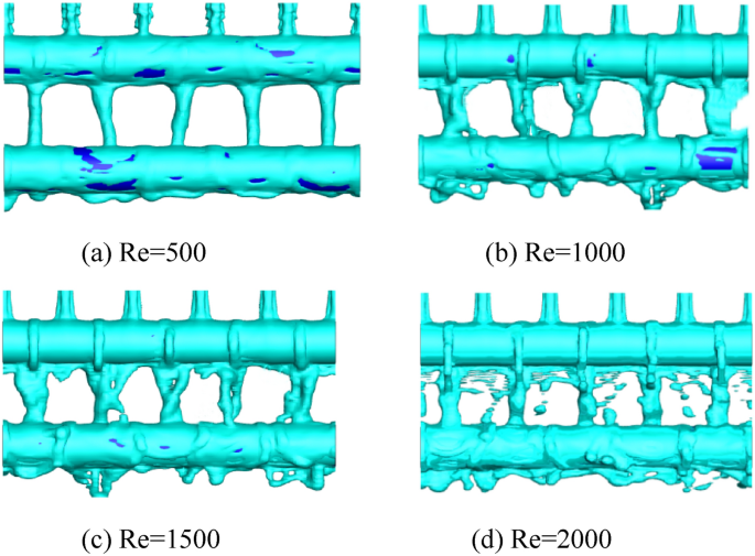
Distribution of shell-side liquid film at Re values of (a) 500, (b) 1000, (c) 1500, and (d) 2000.(Image is generated using Tecplot 360 EX 2021 R2).
Figure 6 shows the axial variation of the liquid film thickness under different Re values at α = 45°, whence it can be seen that the liquid film thickness follows a similar trend at different Re. The refrigerant flowing from the distributor diffuses evenly on both sides after hitting the upper wall of the pipeline, eventually converging in the center to produce the main peak. The secondary peak is formed at the drop position below the distributor. At this position, the liquid film thickness is positively correlated with Re. This is because both the shell-side space pressure outside the heat exchange tube and the residence time of the shell-side coolant on the heat exchange tube remain basically unchanged. Therefore, the shell-side liquid film thickness is positively correlated with the mass flow rate. For Re = 500, 1000, 1500 and 2000, the maximum thicknesses of the main peaks are 0.379, 0.427, 0.539, and 0.774 mm, respectively, while those of the secondary peaks are 0.288, 0.269, 0.258, and 0.233 mm, respectively. Overall, when Re increases from 500 to 1000, the liquid film thickness increases by 32.25% on average. The corresponding average increases in film thickness when Re increases from 1000 to 1500 and from 1500 to 2000 are 7.09 and 21.44%, respectively.
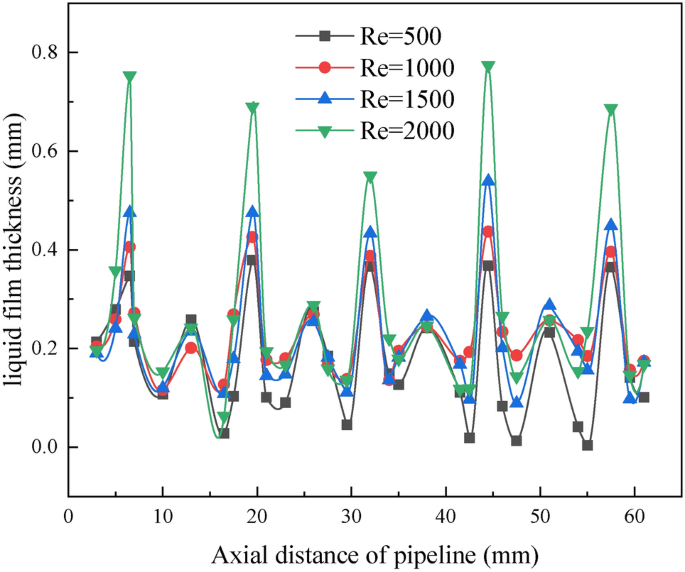
Axial variation of liquid film thickness as a function of Re. (Image is generated using origin 2019b).
Figure 7 shows the circumferential variation of the liquid film thickness on the shell side of the tube-wound heat exchanger at different Re. First, the refrigerant slowly flows out of the distributor towards the upper edge of the heat exchange pipe, before flowing downward to coat the entire pipe. Finally, it converges at the bottom of the pipe and flows downward again to form a liquid column. The results show that under different Re, the liquid film thickness shows a minimum value with increasing α. Overall, when Re increases from 500 to 1000, the film thickness increases by 10.19% on average. The corresponding average increases in film thickness when Re increases from 1000 to 1500 and from 1500 to 2000 are 19.46 and 3.42%, respectively.
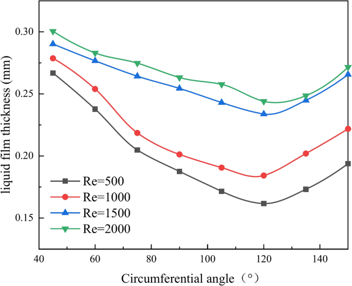
Circumferential variation of liquid film thickness as a function of Re. (Image is generated using origin 2019b).
Diameter of heat exchange tube
In order to study the influence of pipe diameter on the shell-side flow of the spiral-wound heat exchanger, the shell-side falling film flow was simulated at pipe diameters of 6, 8, 10, and 12 mm, respectively, for α = 45°. Figure 8 shows the resulting liquid film thicknesses along the axial direction whence it can be seen that the axial liquid film thickness follows a similar trend under different pipe diameters. Moreover, the thickness of the liquid film shows a periodic change, with the change period being equal to the distance between the two distributors. Taking the region between the two distributors as an example, the thickness of the liquid film initially increases along the axial direction, reaching a maximum at the peak. There is a trough between the peak and the distributor, and there is a secondary peak at the distributor. At a given axial position, the thickness of the liquid film is positively correlated with the pipe diameter. For pipe diameter values of 6, 8, 10, and 12 mm, the maximum thicknesses of the main peaks are 0.539, 0.736, 0.906 and 0.941 mm, respectively, while those of the secondary peaks are 0.235, 0.245, 0.270, and 0.287 mm, respectively. Overall, when the pipe diameter increases from 6 to 8 mm, the liquid film thickness increases by 12.19% on average. The corresponding average increases in film thickness when the diameter increases from 8 to 10 mm and from 10 to 12 mm are 52.16 and 1.86%, respectively.
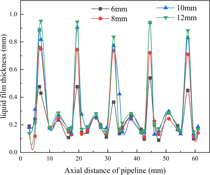
Axial variation of liquid film thickness as a function of pipe diameter. (Image is generated using origin 2019b).
Figure 9 shows the circumferential variation of the liquid film thickness under different pipe diameters. The liquid first slowly flows from the distributor to the upper edge of the heat exchange pipe, then flows downwards to coat the entire pipe. Finally, the liquid re-converges at the bottom of the pipe and flows downwards again to form a liquid column. As α increases, the film thickness gradually decreases. Overall, when the pipe diameter increases from 6 to 8 mm, the liquid film thickness increases by 4.62% on average. The corresponding average increases in film thickness when the pipe diameter changes from 8 to 10 mm and from 10 to 12 mm are 4.85 and 4.55%, respectively.
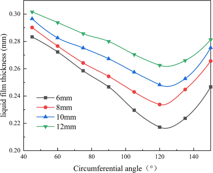
Circumferential variation of liquid film thickness as a function of pipe diameter. (Image is generated using origin 2019b).
Number of distributors
In order to study the influence of the number of distributors on the shell-side flow of the spiral-wound heat exchanger, the shell-side falling film flow was simulated with 5, 6, 7, and 8 distributors, respectively, for α = 45°. Figure 10 shows the resulting axial variation of the liquid film thickness, whence it can be seen that the liquid film thickness follows a similar trend at different numbers of distributors. For the cases with 5, 6,7, and 8 distributors, the maximum thicknesses of the main peaks are 0.539, 0.891, 0.854, and 0.773 mm, respectively, while those of the secondary peaks are 0.235, 0.300, 0.280, and 0.250 mm, respectively. Overall, when the number of distributors increases from 5 to 6, the liquid film thickness of the spiral-wound heat exchanger increases by 37.91% on average; however, when the number of distributors increases from 6 to 7 and from 7 to 8, the liquid film thickness shows average decreases of 8.57 and 13.94%, respectively.
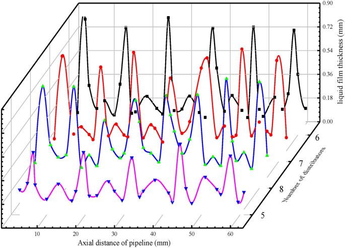
Axial diagram of liquid film thickness as a function of the number of distributors. (Image is generated using origin 2019b).
Figure 11 shows the circumferential variation of the liquid film thickness for different numbers of distributors. The results show that the liquid film thickness follows a similar trend at different numbers of distributors, exhibiting a minimum value at α = 120°. Moreover, at a given value of α, the liquid film thickness is largest when the number of distributors is 6. Overall, when the number of distributors increases from 5 to 6, the liquid film thickness of the spiral wound heat exchanger increases by 27.15% on average; however, when the number of distributors increases from 6 to 7 and from 7 to 8, the liquid film thickness shows average decreases of 9.64 and 5.15%, respectively.
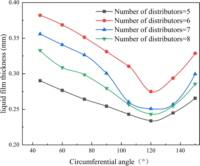
Circumferential variation of liquid film thickness as a function of the number of distributors. (Image is generated using origin 2019b).