
The attenuation of electromagnetic signals is affected by multiple factors, including the excitation frequency, the resistivity of mud and formation, the conductivity of casing and so on. In this study, we conduct numerical research using the parameters of equipment commonly used in the petroleum industry. In order to evaluate the influence of various parameters more accurately, the control variable method is adopted in this paper. That is to say, when discussing a certain parameter, other parameters remain unchanged.
The influence of frequency
Based on the characteristics of electromagnetic wave propagation, the frequency range of the electromagnetic waves studied is set between 5 Hz and 100 Hz. The electrical conductivity of the oil pipe and casing is 107 S/m. The resistivity of the mud is 1 Ω·m, with a relative dielectric constant of 80. The resistivity of the formation is set at 10 Ω·m. The excitation source is located 1000 m underground, with a power of 1 W. In an open-hole well environment, the relationship between the transmitting frequency and the value of the magnetic field around the oil pipe is shown in Fig. 4(a), and the relationship between the change in frequency and the intensity of the received signal on the ground is shown in Fig. 4(b). In a cased well, the relationship between the transmitting frequency and the value of the magnetic field around the oil pipe is shown in Fig. 5(a), and the relationship between the change in frequency and the intensity of the received voltage on the ground is shown in Fig. 5(b).
Fig. 4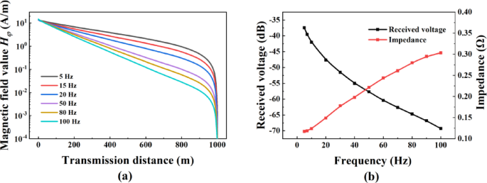
(a) Relationship between transmission frequency and magnetic field value around oil pipe in open hole well. (b) Relationship between frequency in open hole well and ground received voltage and load impedance.
Fig. 5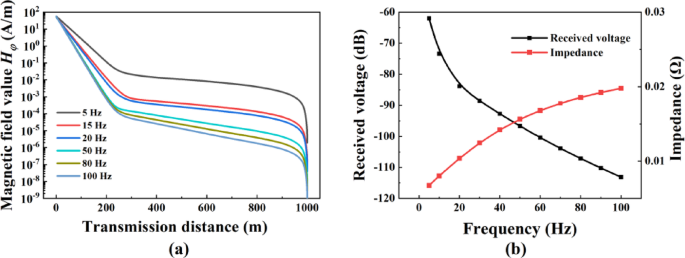
(a) Relationship between transmission frequency and magnetic field value around oil pipe in cased well. (b) Relationship between frequency in cased well and ground received voltage and load impedance.
By comparing Figs. 4 and 5, it can be seen that in the open-hole well environment, whether it is the attenuation of the magnetic field around the oil pipe or the situation of the ground-received voltage, there are significant advantages compared to the cased well. However, it can also be observed that the magnetic field around the oil pipe experiences strong attenuation when approaching the ground. Therefore, when using in-well signal reception, the signal should be received at least 10 m away from the wellhead. As shown in Fig. 4(a), when the frequency is 5 Hz and the transmission distance is 900 m, the magnetic field attenuation is only 26.6 dB, and the attenuation per 100 m is approximately 2.96 dB. When the casing exists, as can be seen from Fig. 5(a), in the initial stage, the magnetic field around the oil pipe shows a sharp and significant decrease in intensity. After the initial intense attenuation, the attenuation rate of the magnetic field gradually slows down. Although the intensity is still decreasing, the decrease value is significantly reduced. For example, when the transmission distance is 200 m and the excitation frequency is 5 Hz, the magnetic field attenuation is about 58.5 dB. However, when the transmission distance is in the range of 200 –900 m, the magnetic field value only attenuates by 16 dB. It can be seen from this that the excitation frequency has a relatively large impact on the near-field region of the antenna.
In Fig. 4(b) and Fig. 5(b), the left vertical axis represents the ground-received voltage, and the right vertical axis represents the external load impedance. It has been found that the ground-receiving effect in the open-hole well is better than that in the cased well environment. Besides, the load impedance of the transmitter in the cased well is much smaller than that in the open-hole well environment, which is the main reason why the wireless electromagnetic transmission system is difficult to be used in the cased well environment. Figure 5(b) shows that when the frequency increases from 5 Hz to 100 Hz, the ground-received voltage decreases by 50.1 dB. Obviously, in order to ensure the transmission distance, a lower excitation frequency should be selected as much as possible. In the follow-up research, the excitation frequency will be set at 5 Hz.
The impact of formation resistivity
When the downhole excitation emits signals outward, the formation is the main transmission medium for the electromagnetic waves radiating outward. During the transmission process of electromagnetic signals, a strong leakage current will occur in the formation. The formation conditions are extremely complex and involve numerous factors. The formation conductivity is a key indicator for measuring the conductive ability of the formation and has a huge impact on the transmission effect of electromagnetic signals. The range of the formation resistivity is set to be from 1 Ω·m to 10,000 Ω·m.
Fig. 6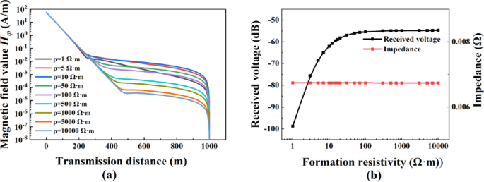
(a) Relationship between formation resistivity and magnetic field value around oil pipe at different transmission distances. (b) Relationship between formation resistivity and ground received voltage and load impedance.
As shown in Fig. 6 (a), when the transmission distance is 200 m, the magnetic field value is scarcely affected by the formation resistivity. However, it can also be found that as the formation resistivity increases, the range of the near-field region of the dipole antenna gradually expands, and the attenuation of the magnetic field value within the overall range increases. The reason is that the high resistivity of the formation causes most of the magnetic field inside the casing to be dissipated in the casing. Looking at the far-field region, it can be observed that when the formation resistivity is in the range of 1 Ω·m to 10 Ω·m, as the formation resistivity rises, the magnetic field attenuation gradually decreases and then tends to stabilize. Moreover, it can be seen that when the formation resistivity is 10 Ω·m, the effect of receiving with the helical loop inside the casing is the best. Figure 6(b) shows the relationship between the formation resistivity and the ground-received voltage and impedance. It can be seen that the increase in the formation resistivity has almost no impact on the load impedance, but the ground-received voltage gradually increases. When the formation resistivity increases to 10 Ω·m, the ground-received voltage tends to stabilize.
The impact of mud conductivity
Due to the differences in geological environments in different regions, the properties of mud in water injection wells also vary greatly. Therefore, mud conductivity is set within the range of 0.1 S/m to 100 S/m, with a relative dielectric constant of 80. Other parameters remain unchanged. Figure 7(a) shows the magnitude of the received magnetic field under different mud environments. Figure 7(b) shows the relationship between the change in the conductivity of the mud and the ground-received voltage.
As can be seen from Fig. 7(a), in the cased well, the conductivity of the mud has a relatively large impact on the magnetic field value around the oil pipe. In the mud with low conductivity, the attenuation of the magnetic field is relatively small. And as can be seen from Fig. 7(b), the factor that has a greater impact on the external load impedance of the transmitter is the conductivity of the mud. When the conductivity of the mud increases from 0.1 S/m to 100 S/m, the impedance decreases by 40 times and the ground-received voltage decreases by 10.9 dB. All in all, the mud with low conductivity is more conducive to the generation and transmission of electromagnetic waves.
Fig. 7
(a) Relationship between mud conductivity and magnetic field value around oil pipe at different transmission distances. (b) Relationship between mud conductivity and ground received voltage and load impedance.
The impact of casing properties
In order to deeply explore the influence mechanism of metal casings on electromagnetic wave transmission, it is necessary to analyze three important characteristics of the casings. Firstly, the electrical conductivity of the casing is one of the key factors affecting electromagnetic wave transmission. The model adopted in this study is consistent with the model mentioned previously. Since casings are usually made of steel, the value range of the casing’s electrical conductivity is set to be from 10⁶ S/m to 2 × 10⁷ S/m. When studying the influence of the casing’s magnetic permeability on signal transmission, we set the electrical conductivity of the casing to be 10⁷ S/m and determine the range of its relative magnetic permeability to be from 1 to 5,000. In addition, the inner diameter of the casing is also a factor that cannot be ignored. Under different drilling conditions, the selected casing sizes will vary. Common inner diameters of casings include 139.7 mm, 177.8 mm, 219.1 mm and so on. In order to study the influence of the casing’s inner diameter on signal transmission, we set the size range to be from 124 mm to 273 mm.
Fig. 8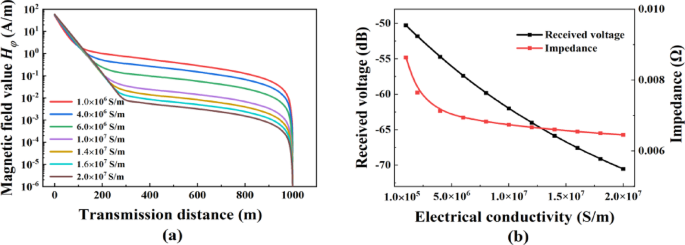
(a) Relationship between casing conductivity and magnetic field value around oil pipe at different transmission distances. (b) Relationship between casing conductivity and ground received voltage and load impedance.
Fig. 9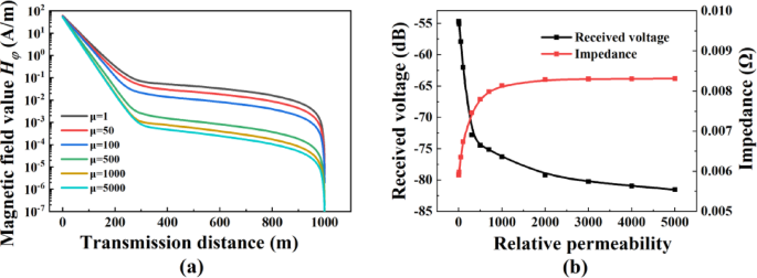
(a) Relationship between casing permeability and magnetic field value around oil pipe at different transmission distances. (b) Relationship between casing permeability and ground received voltage and load impedance.
Fig. 10
(a) Relationship between casing size and magnetic field value around oil pipe at different transmission distances. (b) Relationship between casing size and ground received voltage and load impedance.
As can be seen from Fig. 8(a), as the electrical conductivity of the casing increases, the range of the antenna’s near-field region will increase accordingly, the overall attenuation degree will also increase correspondingly, and the magnetic field value at the corresponding position will become smaller. From Fig. 8(b), it can be known that when the electrical conductivity of the casing increases, the ground-received voltage shows a linear decreasing trend, and the external impedance also decreases significantly. It can be seen that the casing with high electrical conductivity will lead to a substantial increase in electromagnetic losses, which is not conducive to the transmission of electromagnetic waves. Therefore, under the condition of meeting the requirements of practical engineering applications, the casing with low electrical conductivity is more conducive to the transmission of electromagnetic waves.
Figure 9(a) shows the influence of the casing’s magnetic permeability on the magnetic field. It can be clearly seen that the increase in the casing’s magnetic permeability will intensify the attenuation of the magnetic field. According to Fig. 9(b), it can be found that as the relative magnetic permeability continues to increase, the ground-received voltage will experience significant attenuation. For example, when the relative magnetic permeability increases from 1 to 2,000, the magnitude of the ground-received voltage attenuates by 23 dB. However, when the relative magnetic permeability is greater than 2,000, its attenuation effect on the electromagnetic signal will tend to stabilize.
Figure 10(a) presents the strength of the magnetic field around the oil pipe under different casing sizes. When the transmission distance is within 400 m, the larger-sized casing corresponds to a smaller magnetic field attenuation, and the magnetic field strength at the same position is also stronger; while when the transmission distance is greater than 400 m, the situation is different, and the thinner casing instead shows a better transmission effect. Figure 10(b) shows the influence of the casing size on the impedance and the ground-received voltage. It has been found through research that the load impedance will increase as the casing size increases, and the attenuation of the voltage shows a trend of first increasing and then decreasing.
Based on the above analysis results, it can be concluded that the casing with low electrical conductivity, low magnetic permeability, and medium size is more conducive to the transmission of electromagnetic waves.
Influence of contact resistance
In practical engineering application scenarios, the oil pipe and casing usually have a considerable length. Affected by a variety of complex factors, the oil pipe is not always in an ideal state of being completely parallel and upright. Due to the existence of various external forces and internal stresses, the oil pipe may be inclined or bent. There is a high probability that it will come into contact with the metal casing, as shown in Fig. 11(a). And the concept of contact resistance is proposed for the first time. In a metal cased well, contact resistance refers to the local resistance formed due to the physical contact between the oil pipe and the casing. This resistance is jointly determined by the material properties of the contact interface, the contact area, and the mechanical stress. It can be equivalent to a distributed resistance network, and the resistance value generally ranges from 10⁻³ Ω·m to 10⁻⁵ Ω·m. The contact between the oil pipe and the casing is equivalent to two squares with a thickness equal to the distance between the oil pipe and the casing. At the same time, the material conductivity is set to 10⁵ S/m, and the relative magnetic permeability is set to 100. The distance range between the contact position and the excitation source is 0.1 –100 m, and a two – dimensional axisymmetric model is established, as shown in Fig. 11(b). Figure 12(a) shows the relationship between the distance from the contact position to the excitation source and the ground – received voltage, and Fig. 12(b) shows the relationship between the distance from the contact position to the excitation source and the change of load impedance.
Fig. 11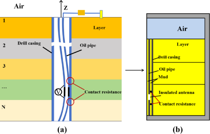
(a) Theoretical model of contact resistance. (b) 2D axisymmetric model.
It has been found through research that the contact position between the oil pipe and the casing has a relatively large impact on both the impedance and the reception of ground signals. Specifically, when the contact position is close to the excitation source, the external load impedance will decrease significantly. Meanwhile, the ground-received voltage will also experience a relatively large degree of attenuation. The reason for this phenomenon is that due to the contact between the oil pipe and the casing, the current will flow from the oil pipe to the casing through the contact point, and most of the energy is consumed at this location, which greatly reduces the radiation efficiency of the asymmetric dipole antenna.
Fig. 12
(a) The relationship between the distance from the contact position to the excitation source and the received voltage on the ground. (b) The relationship between the distance from the contact position to the excitation source and the change of the load impedance.