Structural characterizations
Two different series of heterostructures with β-W (10 nm)/CFB (4, 6, 8,10 nm)/CuOx (3 nm) and β-W (10 nm)/CFB (4, 6, 8,10 nm)/C60 (25 nm) stackings have been fabricated on Si/SiO2 (300 nm) substrates (Fig. 1a, b). Along with that the CFB/CuOx and CFB/C60 bilayers were also prepared for the investigation of magnetization dynamics and spin-orbital pumping phenomena. The stacking and nomenclature of different heterostructures are mentioned in Table 1. The grazing incidence X-ray diffraction (GIXRD) measurements were performed for all the heterostructures. The GIXRD pattern of WCF1 heterostructure is shown in Fig. 1c. The presence of (200), (210), (211), and (321) Bragg peaks confirm the stabilization of β-phase of W. A similar type of GIXRD pattern is also observed for other heterostructures. The X-ray reflectivity (XRR) patterns of WCF1 and WCFO1 heterostructures are shown in Fig. 1d. The XRR data of all the heterostructures are fitted with GenX software, and the desired thickness of individual layers are confirmed from the XRR fittings. Further, the details of growth and structural characterizations of β-W, C60, and naturally oxidized Cu (CuOx) are mentioned elsewhere7,15. The nonlinear I–V characteristics along with the presence of Bragg peaks for CuOx in the GIXRD patterns of 10 and 20 nm Cu/CuOx films grown on Si/SiO2 (300 nm) confirm the presence of CuOx7.
Fig. 1: X-ray diffraction and X-ray reflectivity for β-W phase and individual layer thickness analysis.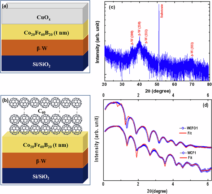
Schematics of sample stacking for a WCF and b WCFO series of heterostructures. c GIXRD pattern of β-W (10 nm)/CFB (4 nm)/CuOx (3 nm) [WCF1] heterostructure and d XRR patterns and the corresponding fits with GenX software for β-W (10 nm)/CFB (4 nm)/CuOx (3 nm) [WCF1] and β-W (10 nm)/CFB (4 nm)/C60 (25 nm) [WCFO1] heterostructures.
Table 1 Stacking of different heterostructures with their corresponding nomenclatures
The surface morphology of all the heterostructures imaged by atomic force microscopy (AFM) is presented in Fig. 2. The topography changes for different heterostructures in the WCF series capped with CuOx layers. The root mean square (RMS) roughness for WCF1, WCF2, WCF3, and WCF4 heterostructures are found to be ~3.68 nm, ~3.02 nm, ~1.5 nm, and ~4.2 nm, respectively. Although the thickness of CuOx capping layer is same for all the heterostructures in the WCF series, the roughness is found to be random. This might be due to the different nature of the natural oxidation of Cu as it is occurring in the ambient environment in an uncontrolled manner. Such type of oxidation can play an important role in governing the magnetization dynamics properties of these heterostructures. We have also performed the AFM imaging of 6 and 10 nm thick CFB films (Fig. S1 of supplementary information). The RMS roughness is found to be similar (~0.6 nm) for both the films, further inferring the change in roughness in the WCF series is due to the top CuOx layer. Whereas the topography of the heterostructures in the WCFO series, when capped by the organic C60 does not change much. The RMS roughness of all the heterostructures in the WCFO series is found to be similar (~0.8 to ~1 nm), in contrast to the heterostructures in the WCF series.
Fig. 2: Analysis of surface morphology of different heterostructures with CuOx and C60 over layers.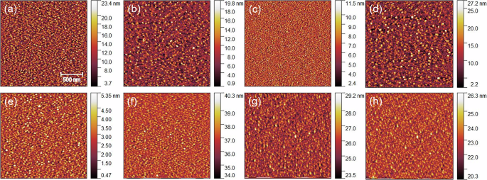
AFM topography of a WCF1, b WCF2, c WCF3, d WCF4, e WCFO1, f WCFO2, g WCFO3, and h WCFO4 heterostructures. Scale bars correlating the color to the height are shown to the right of each image.
Static magnetic characterizations
The angle-dependent in-plane hysteresis loops were traced for all the heterostructures via magneto-optic Kerr effect (MOKE) microscopy. The magnetization reversals for WCF1 and WCFO1 heterostructures along the easy axis are presented in Fig. 3a, b. The easy axis denoted as 0∘ is the orientation of the magnetic field along the sample surface, where a sharp and squared magnetization reversal is observed. Whereas the hard axis, represented as 90∘, is associated with coherent magnetization reversal with the least squared loop. Both the heterostructures exhibit the presence of uniaxial magnetic anisotropy, which can be attributed to the oblique incident sputtered growth of the FM layer. A similar type of magnetization reversal has also been observed for other heterostructures capped with CuOx and C60. A significant change in the coercive field (Hc) is not evident when the capping layer is changed from CuOx to C60. The capping of organic C60 on 3d transition ferromagnetic metals usually enhances the magneto-crystalline anisotropy (MCA) energy and, consequently, the coercive field owing to interfacial hybridization13,14. However, the modification of magnetic anisotropy energy is highly dependent on the crystallinity, orbital orientation, exchange-correlation length, etc14. The as-deposited CFB is amorphous in nature and usually composed of nano-crystalline grains in the 1–10 nm range22. The presence of relatively smaller in size and large numbers of grains can statistically average out the magneto-crystalline anisotropy and reduce the effective anisotropy energy (Keff) in CFB22,23. The reduction in Keff can enhance the ferromagnetic exchange correlation length as per the following equation22.
$${L}_{ex}=\pi {(\frac{{A}_{eff}}{{K}_{eff}})}^{\frac{1}{2}}$$
(1)
Here, Aeff represents the effective exchange stiffness, and Lex represents the range of effective exchange interaction range. This is also evident as the hysteresis loops with high squareness along the easy axes for both the heterostructures (Fig. 3a, b). Further, a relatively larger magnetic domain is observed for CFB (Fig. 3d–g) in all the heterostructures compared to the previous report24. This also signifies the presence of a larger exchange correlation length. As the organic overlayer primarily modifies the MCA, the amorphous nature of CFB can explain the similar Hc for both inorganic and organic capping layers as well as the soft magnetic nature of WCF1 and WCFO1. The ferromagnets with low Hc are quite important from the spintronics application point-of-view. Interestingly, the Hc of the hysteresis loops measured along the easy axes for different heterostructures increases gradually with the increase in CFB thickness (Fig. 3c). The gradual increase of Hc with thickness is observed for both inorganic and organic capping layers. This reflects the systematic growth and nucleation of different layers in both the series of heterostructures considered for the present study. Previously, a similar type of thickness-dependent Hc has been observed for as-deposited amorphous CFB with higher thicknesses22,25. This has been attributed to the increase in grain size of the nano-crystallites of CFB. The larger grains with a reduction in a number of grains might not average out the local MCA. Hence, a larger Keff and, consequently, a larger Hc can be expected with the increase in CFB thickness.
Fig. 3: Static magnetic properties with CuOx and C60 over layers.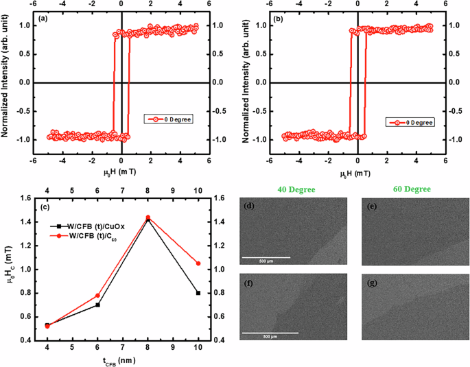
Hysteresis loops of a β-W (10 nm)/CFB (4 nm)/CuOx (3 nm) [WCF1] and b β-W (10 nm)/CFB (4 nm)/C60 (25 nm) [WCFO1] heterostructures measured along easy axis, c CFB thickness dependent Hc of various heterostructures, and magnetic domain images of d, e WCF1 and f, g WCFO1 heterostructures.
Magnetization dynamics investigation
The magnetization dynamics of all the heterostructures in both the WCF and WCFO series were investigated by lock-in-based ferromagnetic resonance (FMR) technique. The heterostructures were placed in a flip-chip manner on top of the co-planner waveguide (CPW) and the FMR spectra were recorded in the 4–17 GHz range. The field-swept FMR spectra at different resonance frequencies for WCF1 and WCFO1 heterostructures are shown in Fig. S2 (supplementary information). A similar type of FMR spectra were recorded for all the heterostructures. Each spectrum was fitted by the derivative of symmetric and anti-symmetric components of the Lorentzian function15:
$$FMRSignal={K}_{1}\frac{4(\Delta H)(H-{H}_{res})}{{[{(\Delta H)}^{2}+4{(H-{H}_{res})}^{2}]}^{2}}-{K}_{2}\frac{{(\Delta H)}^{2}-4{(H-{H}_{res})}^{2}}{{[{(\Delta H)}^{2}+4{(H-{H}_{res})}^{2}]}^{2}}+Offset,$$
(2)
where K1 and K2 are the anti-symmetric and symmetric absorption coefficients, respectively. The resonance field (Hres) and linewidth (ΔH) extracted for various resonance frequencies from the Lorentzian fit of the field-dependent FMR absorption are shown in Fig. 4. The Hres-dependent f of different heterostructures are plotted in Fig. 4a, b. The f vs. Hres plots are fitted by using the Kittel’s equation15:
$$f=\frac{\gamma }{2\pi }\sqrt{({H}_{K}+{H}_{res})({H}_{K}+{H}_{res}+4\pi {M}_{eff})},$$
(3)
where
$$4\pi {M}_{eff}=4\pi {M}_{s}+\frac{2{K}_{s}}{{M}_{s}{t}_{FM}}$$
and HK, Ks, and tFM are the anisotropy field, interface magnetic anisotropy energy density, and the thickness of FM, respectively. Here, γ is the gyromagnetic ratio, and 4πMeff represents the effective magnetization. The 4πMeff extracted from the fitting gives similar values as compared with the saturation magnetization value (4πMs) calculated from the SQUID-VSM (see supplementary information). The magnetic Gilbert damping, which encompasses pivotal information regarding magnetization relaxation, spin wave propagation, and spin-pumping into the adjacent non-magnetic layers, is investigated from the resonance frequency-dependent FMR linewidth behavior (Fig. 4c, d). A linear dependency of ΔH on resonance frequency is evident for all the heterostructures in both the WCF and WCFO series. The small oscillations observed in ΔH vs. f curve at higher frequencies for the WCFO1 sample could be due to the presence of TMS, which can affect the linear behavior of ΔH vs. f curve26. The thickness of CFB is ~4 nm in WCFO1 heterostructure, which is smaller compared to the thickness of CFB of other heterostructures. When the thickness of the FM layer is lowered, the contribution of TMS and/or SML becomes relatively more prominent, which could lead to the non-linearity in ΔH vs. f curve17,18,26. The ΔH vs. f plots are fitted by the following equation to separate the intrinsic and extrinsic contribution to the precessional damping15:
$$\Delta H=\Delta {H}_{0}+\frac{4\pi {\alpha }_{eff}}{\gamma }f$$
(4)
Here, ΔH0 is known as the linewidth broadening caused by the sample imperfections representing the extrinsic contribution. The αeff represents the intrinsic contribution to the damping and is also known as effective Gilbert damping. The αeff of different heterostructures were evaluated from the linear fits of ΔH vs. f plots using equation (4). The 1/tCFB dependent αeff of different heterostructures from both series are shown in Fig. 5a. Interestingly, the αeff for the WCFO series is found to be larger compared to that with the heterostructures in the WCF series. Especially, the enhancement is more prominent for the heterostructures with thinner CFB layers. This infers a significant modification in magnetization dynamics when the β-W/CFB bilayers are capped by inorganic and organic layers. The enhancement of Gilbert damping when the HM/FM bilayers are capped by C60 can have different origins. The additional spin-pumping into the organic layer, two-magnon scattering caused by the interfacial SOC and magnetic roughness at the CFB/C60 interface, or interfacial spin memory loss could be the reason for this significant enhancement17,18,27. Previously the enhancement in magnetic damping in Py/organic bilayer has been observed, which could be due to spin-pumping from Py28. Although the static magnetization properties of the heterostructures capped by C60 and CuOx remain similar, the magnetization relaxation phenomenon under microwave excitation presents a clear difference. The αeff for both the CuOx and C60 capping increases linearly with 1/tCFB and can be well fitted with the following equation19:
$${\alpha }_{eff}={\alpha }_{CFB}+{g}_{eff}^{\uparrow \downarrow }\frac{g{\mu }_{B}}{4\pi {M}_{s}{t}_{CFB}}$$
(5)
where αCFB is the intrinsic damping of the CFB layer. g, μB, and tCFB are the Landé g factor (2.1), Bohr magneton, and thickness of the CFB layer, respectively. The slopes of the linear fit for WCF and WCFO series are found to be significantly different and can influence the spin-orbital to charge interconversion phenomenon in β-W/CFB/CL heterostructures. The \({{\rm{g}}}_{eff}^{\uparrow \downarrow }\), which is the real part of spin mixing conductance, were calculated for WCF and WCFO series by considering the Ms value ~1200 emu/cc, measured by SQUID-VSM (see supplementary information (Fig. S3)). The \({{\rm{g}}}_{eff}^{\uparrow \downarrow }\) values for WCF and WCFO series are found to be 2.2 × 10¹⁹ m−2 and 3.5 × 10¹⁹ m−2, respectively. However, the hybrid heterojunction formed by the amorphous CoFeB with low SOC polycrystalline CuOx and organic C60 could facilitate the interfacial phenomena like TMS and SML, which in turn can modify the interfacial transparency and, consequently, the magnetic damping value and \({{\rm{g}}}_{eff}^{\uparrow \downarrow }\)29. Further, it is important to note that the heterostructures investigated in this work comprise CFB thickness in 4–10 nm range. The αeff vs. 1/tCFB behavior may deviate from the linear dependency for thinner CFB layers due to the contributions from TMS and SML30. However, the TMS and SML are not expected to play a significant role in thicker CFB as in our case. The organic CL could induce local orbital hybridization and, hence, the modification of interface electronic structure and local magnetic anisotropic energy. This could enhance the TMS as it is usually proportional to the square of \(\frac{2{K}_{s}}{{M}_{s}}\)30. The 4πMeff vs. 1/tCFB behavior for all the heterostructures is shown in Fig. 5b. The 4πMeff varies linearly with 1/tCFB for the WCFO series, whereas the linear behavior is absent for the WCF series. This indicates the Ks, which represents the interfacial magnetic anisotropy energy density for both types of interfaces on either side of the FM layer, may not be the same for all the heterostructures in the WCF series. The Cu capping in the WCF series gets naturally oxidized to form CuOx, and the oxidation level could be different in different heterostructures as it is not controlled experimentally. This behavior is also consistent with randomness in the surface topographic images observed for different heterostructures in the WCF series. Hence, the interfacial anisotropy in CFB/CuOx could be modulated for different heterostructures in the WCF series as the 3 nm Cu is expected to be completely oxidized7,8,31. Whereas the thicker 25 nm C60 capping presents a similar FM/C60 interface for all the heterostructures in the WCFO series and hence, the similar Ks for all the heterostructures with organic capping. Nevertheless, a rough estimation of slope from the linear fit of 4πMeff vs. 1/tCFB behavior in Fig. 5b can shed light on the possible origin of enhanced Gilbert damping for the WCFO series. As it can be seen in Fig. 5b, the slope (and hence the \(\frac{2{K}_{s}}{{M}_{s}}\) (from equation (3))) value is larger for the WCFO series compared to the WCF series. This infers a possible local short-range interfacial hybridization upon C60 capping, which could possibly modify the Ks and induce relatively faster magnetization precession via magnon-magnon scattering32. Further, the interfacial spin memory loss due to ISOC at the CFB/C60 interface could also enhance the magnetic damping as the C60 is predicted to possess curvature-induced SOC11.
Fig. 4: Ferromagnetic resonance investigation of different heterostructures.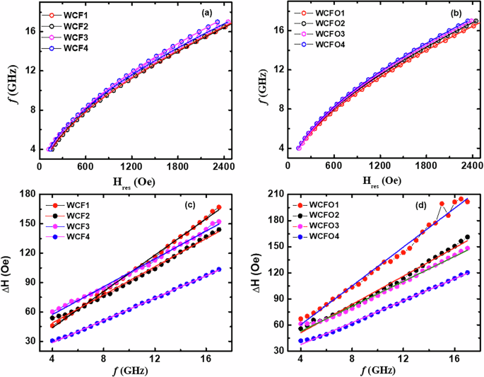
a, b Frequency (f) vs. resonance field (Hres) and c, d linewidth (ΔH) vs. frequency (f) behavior for various heterostructures. The solid lines are the best fits to equations (3) and (4).
Fig. 5: Analysis of CFB thickness dependent effective Gilbert damping and effective magnetization.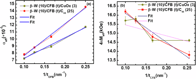
1/tCFB dependent a αeff and b 4πMeff for various heterostructures and the corresponding linear fits to equation (5) and (3).
In order to further understand the magnetization dynamics of the heterostructures, the spin-orbital to charge conversion phenomenon of all the samples in the WCF and WCFO series was investigated. The measurements were performed from ϕ ~ 0∘ to ϕ ~ 360∘, where ϕ represents the angle between the measured voltage direction and perpendicular direction to the applied magnetic field during ferromagnetic resonance. The field-swept FMR and corresponding measured DC current across the WCF1 sample is shown in Fig. 6a. The sign of the measured DC current (IDC ~ VMEAS/R:VMEAS is the measured DC voltage and R is the device resistance) gets reversed for opposite external field direction, inferring the spin-orbital pumping mechanism. A similar type of IDC vs. H pattern is observed for all the heterostructures in the WCF and WCFO series. The IDC vs. H plots are fitted by the following Lorentzian function to separate the symmetric (ISYM) and asymmetric (IASYM) components of the measured DC currents15:
$${I}_{DC}={I}_{SYM}\frac{{(\Delta H)}^{2}}{{(\Delta H)}^{2}+{(H-{H}_{res})}^{2}}+{I}_{ASYM}\frac{(\Delta H)(H-{H}_{res})}{{(\Delta H)}^{2}+{(H-{H}_{res})}^{2}}$$
(6)
The ISYM around the resonance frequency extracted for ϕ ~ 0∘ also reverses the sign for ϕ ~ 180∘ (Fig. 6b), as expected for typical ISHE measurements. The symmetric voltage component (VSYM) comprises the spin-pumping induced DC voltage VSP along with spin rectification effects arising due to anisotropic magnetoresistance (AMR) and anomalous Hall effect (AHE). Further, the β-W has a negative spin Hall angle, whereas the spin/orbital Hall angle of C60 and CuOx are found to be positive7,8,11,20. Hence, the IDC at the β-W/CFB interface and CFB/CL interface are expected to be added up according to the symmetry. The angle-dependent ISYM plots for WCF1, WCFO1, WCF2, and WCFO2 heterostructures are shown in Fig. 7a–d. The data are fitted with the following equation to exclude the spin rectification effects and evaluate the spin-orbital pumping current, ISP15:
$$\begin{array}{l}{I}_{SYM}={I}_{SP}Co{s}^{3}(\phi )+{I}_{AHE}Cos(\phi )Cos(\theta )\\ \qquad\quad\;+\,{I}_{SYM}^{AMR\perp }Cos(2\phi )Cos(\phi )+{I}_{SYM}^{AMR\parallel }Sin(2\phi )Cos(\phi )\end{array}$$
(7)
Here, θ is the phase between the RF electric field and the magnetic field in the medium. IAHE, \({I}_{SYM}^{AMR\perp }\), \({I}_{SYM}^{AMR\parallel }\) is the charge current arising due to AHE, perpendicular component of current arising due to AMR and parallel component of current arising due to AMR, respectively. A similar type of fitting of ISYM vs. ϕ plots has also been performed for other heterostructures to evaluate the ISP (\({I}_{SP}\, \sim \,\frac{{V}_{SP}}{R}\), where R is the device resistance).
Fig. 6: Spin-orbital pumping with CuOx over layer.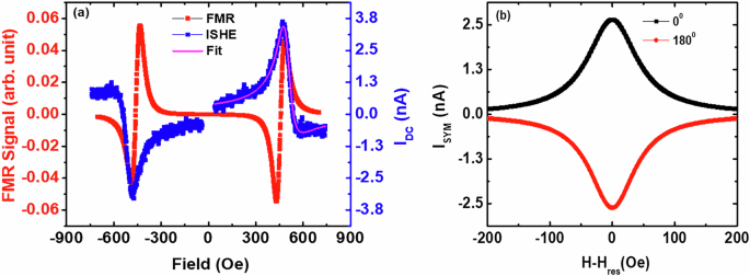
a Magnetic field dependent FMR spectrum and measured DC current (IDC) and b symmetric components of DC current (ISYM) for β-W (10 nm)/CFB (4 nm)/CuOx (3 nm) [WCF1] heterostructure measured at 7 GHz frequency.
Fig. 7: Angle dependent analysis of spin-orbital pumping induced charge current.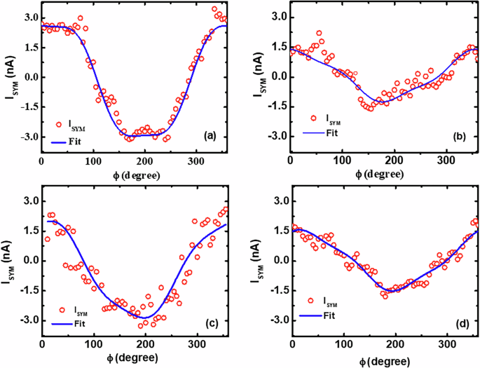
Angle-dependent symmetric components of DC current (ISYM) for a WCF1, b WCFO1, c WCF2, and d WCFO2 heterostructures measured at 7 GHz frequency.
The ISP for all the heterostructures in the WCF and WCFO series are plotted in Fig. 8a. Interestingly, the ISP values for the heterostructures with CuOx capping are found to be larger compared to that with organic C60 capping. This trend is of the opposite nature to that of αeff, where the magnetization relaxation is found to be faster for the organic C60 capping. To further understand this anti-correlation effect, we measured the spin-orbital to charge conversion of CFB (7 nm)/CuOx (3 nm) and CFB (7 nm)/C60 (25 nm) heterostructures. The ISYM for both the heterostructures reverses sign when the ϕ is changed from 0∘ to 180∘ (Fig. 8b), confirming the spin-orbital pumping in both the bilayers with non-magnetic low SOC over layers.
Fig. 8: Enhanced spin-orbital pumping with CuOx compared to C60 over layer.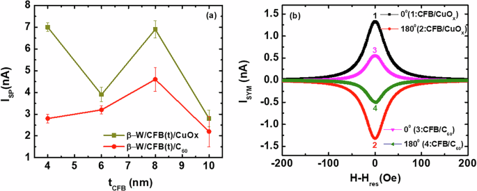
a CFB thickness-dependent spin-orbital pumping current (ISP) and b symmetric components of DC current (ISYM) for CFB (7 nm)/CuOx (3 nm) and CFB (7 nm)/C60 (25 nm) bilayers.