Programming large-area geometric phase beam steering metasurfaces
The conventional fabrication of large-area metasurfaces is complex and requires several lithography steps, incompatible with the requirements of rapid prototyping. Direct laser writing of metallic antennas with the plasmonic PCM IST instead offers a promising platform for the rapid development of complex phase-modulated metasurfaces. The large-area metasurfaces investigated are directly optically written in 100 nm amorphous IST on top of a transparent CaF2 substrate with precise laser pulses (see Fig. 1A). In particular, we applied the direct laser writing system Photonic Professional GT from Nanoscribe equipped with highly precise galvo mirrors to redirect the laser beam on the sample and induce the crystallization process (see Methods). While amorphous IST exhibits dielectric behavior with a constant permittivity of 14, its crystalline phase follows a metallic Drude-like behavior (ε’ 24. The real part of the permittivity for amorphous and crystalline IST is shown in Fig. 1B (see Supplementary Note 1 for more details). A comparison of the permittivity of the plasmonic PCM IST with dielectric PCMs such as Ge3Sb2Te6 and Ge2Sb2Se4Te1 and the phase transition material VO2 is shown in Supplementary Note 2. Consequently, it is possible to directly program entire large-area metasurfaces by locally crystallizing spatially varying nanoantennas within the amorphous IST. Full 2π-phase control within the metasurfaces fabricated is achieved by rotating the antennas from zero to 180 degrees and illuminating the metasurface with circularly polarized light. This concept is also known as the Pancharatnam–Berry phase or geometric phase. The rotation angle \(\beta\) directly translates to the phase of the scattered light \(\phi\) via:
$$\phi=2\cdot \beta$$
(1)
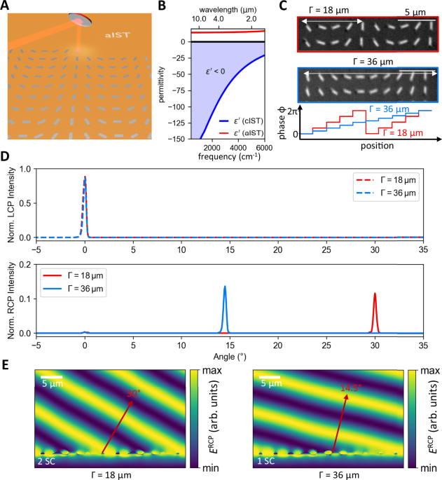
Fig. 1: Beam steering metasurface with IST.
A Concept of programming large-area geometric metasurfaces by optically crystallizing rotated IST rod antennas. Controlling the rotational angle of the rod antennas results in full 2π phase control of the metasurface. B Real part of the permittivity for amorphous and crystalline IST. In the crystalline phase, IST shows metallic behavior (ε’ C Light microscope images of two different beam steering metasurfaces with supercell periods Γ of 18 µm and 36 µm. The phase increases from 0 to 2π along the supercell period. The scale bars are 5 µm. D Measured beam intensities for two different beam steering metasurfaces with supercell periods of 18 and 36 µm. The RCP component of the circularly polarized light is deflected, while the initial LCP light is not affected. E Simulated RCP electric field for incident LCP light for the two metasurfaces. The measured beam deflection is well reproduced for both supercell (SC) periods.
The phase is only controlled by the rotation of the antenna and the chirality of the scattered light is reversed with respect to the incident light, allowing for a clear distinction of the incident light from the scattered light36. A more detailed description of this geometric phase concept can be found in Supplementary Note 3.
The employed antennas featuring a length of 2.5 µm are designed to be resonant at a wavelength of 9 µm, which is the operation wavelength of the infrared quantum cascade laser and the employed quarter-wave plates. Utilizing the resonance wavelength of the nanoantennas ensures maximum scattering and, consequently, maximum efficiency of the metasurfaces investigated. Note, that this choice of wavelength does not display a limit of the demonstrated concept and any other infrared wavelength would be also possible. Measured transmittance spectra of crystallized IST antennas for different lengths can be found in Supplementary Note 4.
First, we investigate two beam steering metasurfaces with spatially varying antennas along the supercell period \(\Gamma\). Within the supercell period, the phase gradient varying from 0 to 2π is determined by the rotation angle of the antennas. Engineering the supercell period \(\Gamma\) leads to the deflection angle via3:
$$\theta=\arcsin \frac{\lambda }{\Gamma }$$
(2)
The operation wavelength is set to 9 µm and two metasurfaces with supercell periods of 18 and 36 µm are designed, leading to theoretically calculated deflection angles of 30° and 14.5°, respectively. The period between individual antennas is set to 4 µm with an antenna length and width of 2.5 and 0.7 µm, respectively. The height of the antennas is limited by the thickness of the IST layer, resulting in a maximum antenna height of 100 nm. Light microscope images of the optically crystallized metasurfaces are shown in Fig. 1C. Note that for the beam steerer with a corresponding supercell period of 18 µm, two adjacent supercells are displayed. The entire metasurface with a size of 4 × 4 mm² consists of 1 million individual antennas with varied orientations fabricated within 2.5 h. The phase difference introduced between adjacent antennas is given by 2π/N, with N referring to the number of antennas within the supercell.
Afterward, we characterize the deflected beam transmitted through the metasurfaces with a home-build setup (see Methods). The incident left-handed circularly polarized (LCP) beam is transmitted through the metasurface, while the scattered right-handed circularly polarized (RCP) beam is deflected according to formula 2. The detector is rotated to measure the angle-resolved beam intensity. Applying a second quarter-wave plate combined with a linear polarizer allows for clear distinction between both polarization chiralities.
Figure 1D displays the measured laser intensities after passing both beam steering metasurfaces dependent on the angle and polarization chirality. The initial LCP chirality (dashed curves) is transmitted through the metasurface, showing maximum intensity at 0° deflection. In contrast, light with the opposite RCP chirality (solid lines) is deflected according to formula (2). Here, the metasurface with a supercell period of 18 µm exhibits a peak for the deflected RCP light at 30°, while the metasurface with the larger supercell period of 36 µm reveals a deflection angle of 14.5°. The experimentally measured beam intensities are in very good agreement with numerical far-field simulations (see Supplementary Note 5). The efficiency of the metasurfaces is determined by comparing the intensity of the deflected light with the unaffected transmitted light, revealing values around 10%. We attribute the higher efficiency of the metasurface with a larger supercell period of 36 µm to smaller phase increment steps due to the doubled amount of rotated antennas compared to the metasurface with a supercell period of 18 µm (c.f. Figure 1C bottom).
We performed field simulations of the RCP electric field transmitted through the metasurface for incident LCP light, as shown in Fig. 1E. The RCP component is deflected by 30° for the metasurface with a supercell period of 18 µm, and by 14.5° for the metasurface with a supercell period of 36 µm, respectively. Hence, the experimentally obtained deflection angles are well reproduced with electric field simulations and numerical far-field simulations.
Moreover, our designed beam steering metasurface is robust against fabrication imperfections due to the broad electric dipole resonances of the IST antennas. We demonstrate that even length variations of ±20% perform similarly without a significant decrease in performance (see Supplementary Note 6).
Focusing infrared radiation with a metalens
In addition, we investigate a metalens consisting of rotated crystalline IST rod antennas which focus the converted RCP radiation to a focal spot 11.5 cm behind the metasurface (see sketch in Fig. 2A). The large focal distance of the metalens is chosen arbitrarily to ease subsequent measurement by ensuring enough distance between the metasurface and the focal spot. The applied phase pattern of the metasurface is shown in Fig. 2B, featuring concentric rings of equal phases calculated with:
$$\phi \, (r)=\frac{2\pi }{\lambda }(\sqrt{{r}^{2}+{f}^{2}}-f)$$
(3)
Fig. 2: Metalens with IST.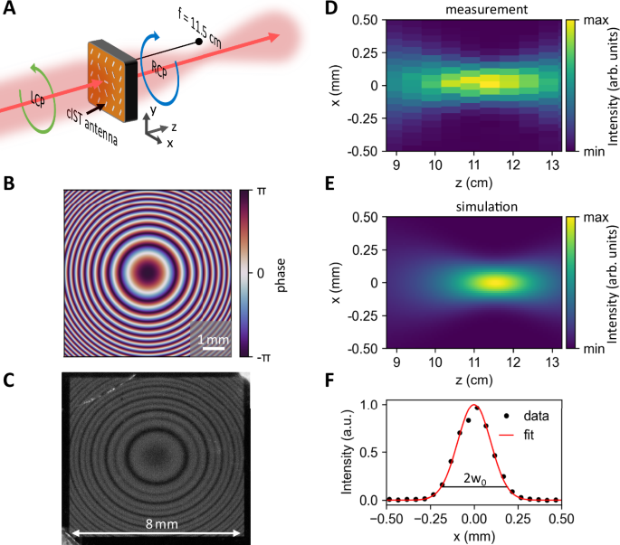
A Schematic sketch of the working principle applied. The incident LCP light is converted to RCP radiation and focused according to the designed focal length. B Imprinted phase profile of the metalens consisting of concentric rings with equal phases. C Photograph of the fabricated 8 × 8 mm² metasurface consisting of 4 million rotated IST antennas. D Measured intensity distribution in the xz-cross section clearly displaying a focal spot 11.5 cm from the metasurface. E Simulated intensity distribution of a metasurface with the applied phase pattern from (B). F Cross-section of the measured focal spot revealing a beam waist w0 of 189 µm.
Here, f denotes the focal length of 11.5 cm and the operation wavelength λ of the metasurface is again set to 9 µm, while r determines the radial antenna position.
Figure 2C displays a photograph of the fabricated 8 × 8 mm² large-area metasurface with each antenna resembling a fixed phase value. The period between adjacent antennas is set to 4 µm, and the exact orientation of each antenna at different positions on the metasurface is calculated with Eq. 3, leading to a nearly continuously varying phase pattern. The entire metasurface consists of 4 million single antennas fabricated in 8 h. The same procedure is used for all the following metasurfaces.
The corresponding intensity distribution measured in the xz-cross-section is shown in Fig. 2D (see Methods about the measurement procedure). A clear focal spot with maximum intensity is observed at 11.5 cm from the metasurface. Our experimental results are supported by numerical simulations done with the Python package LightPipes by simulating the propagation of the incident Gaussian beam transmitted through the metasurface with the phase pattern of Fig. 2B. The simulations shown in Fig. 2E validate the focal spot at 11.5 cm from the metasurface with a comparable beam waist diameter in the focal spot. Finally, we investigate the diameter of the focal spot in Fig. 2F exhibiting a beam waist of 189 µm by fitting a Gaussian function to the measured intensity. The large beam waist is caused by the intrinsic ultra-low numerical aperture (NA) of 0.03 due to the large focal length of the metasurface. The low NA is only chosen for simplified measurement of the focal spot. Our approach of patterning IST metasurfaces allows for metalenses with larger NA too. The retrieved beam parameter product of the laser after passing the metasurface is close to the optimal value, confirming that our metasurface preserves the intrinsic beam quality (see Supplementary Note 7).
Beam-shaping exploiting orbital angular momenta
Generally, the concept of orbital angular momentum (OAM) has gained much interest in the past years37. The characteristic vortex beams consisting of different OAM modes feature a ring-like intensity distribution combined with helical phase factors \(\exp ({il}\phi )\), with \(l\) referring to the topological charge and \(\phi\) the azimuthal angle. The orthogonal OAM modes can be superimposed to increase information capacity and boost optical communication systems38,39.
Here, we design three beam-shaping metasurfaces carrying an OAM in addition to the intrinsic spin angular momentum mediated by the polarization of the light. Therefore, we employ three helical phase patterns with topological charge l of one, three and five (see Fig. 3A). As stated before, the orientation of the antennas is calculated according to the exact position onto the metasurface.
Fig. 3: Encoded orbital angular momentum.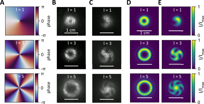
A Applied helical phase patterns carrying an orbital angular momentum of 1, 3, and 5 for three different metasurfaces. B Measured far-field intensity patterns of the beam 60 cm from the metasurface displaying a ring-like structure with increasing diameter for higher orbital angular momenta. C Direct interference of the unaffected incident light with the scattered light from the metasurface leads to a spiral pattern with the number of spiral arms revealing the orbital angular momentum. D Simulated far-field intensity pattern of the helical phase profiles demonstrating similar ring patterns compared to (B). E Simulated spiral patterns due to the interference of the incident Gaussian beam and the transformed beam after passing the metasurface reveal very good agreement between experiment and simulation.
The corresponding far-field intensity measurements of our metasurfaces can be seen in Fig. 3B. The diameter of the observed rings increases, pointing towards different topological charges. The measured intensity cross-section along the rings can be found in Supplementary Note 8. The determination of the intrinsic OAM is achieved by direct interference of the unaltered beam with the light carrying the OAM after passing the metasurface (see Methods for more details). The results are shown in Fig. 3C. Here, the number of observable spiral arms is directly associated with the topological charge. The first image for l = 1 features only one spiral arm, while the second image for l = 3 features three spiral arms and so on, verifying the OAM carried by the photons after passing the metasurface.
Numerical simulations of a Gaussian beam imprinted with the corresponding phase profiles in Fig. 3A are shown in Fig. 3D. Characteristic ring-like patterns associated with doughnut modes with increasing diameter for increasing topological charges appear with diameters comparable to the experimentally obtained images. Figure 3E displays far-field intensity simulations of the OAM beam superimposed by the incident Gaussian beam, revealing the spiral arms as described before. The simulations are in very good agreement with the experimental data.
Enlarged infrared holography with a multifunctional metasurface
The vast flexibility of direct programming complex phase patterns with IST is demonstrated by designing a holographic phase pattern with the Gerchberg–Saxton algorithm (see Methods) to create a specific infrared hologram in the far field. Because the size of the designed holographic image is small and, therefore, challenging to measure, we superimpose the retrieved phase pattern of the hologram with the phase pattern of a magnifying lens. This highlights the ability to combine multiple functionalities within a single metasurface and leads to simplified imaging of the resulting hologram with a size of several centimeters. The concept is sketched in Fig. 4A. The targeted far-field intensity pattern is displayed in Fig. 4B, showing the letters “ir nano” with uniform intensity. The final calculated phase pattern combined with the phase pattern of the lens for the designed hologram 60 cm from the metasurface can be seen in Fig. 4C. Here, the phase values are simply added to each other. The photograph of the fabricated 8×8 mm² metasurface shows a similar pattern caused by scattering of the visible light (c.f. Fig. 4D). The measured hologram in combination with numerical simulation is shown in Fig. 4E for different distances behind the metasurface. While for small distances (e.g., 20 cm behind the metasurface), no clear image is observed, at larger distances around 60 cm behind the metasurface, the letters “ir nano” are clearly resolvable. Due to the magnifying lens, the size of the hologram increases with further distance to the metasurface. The experimental data and the simulations agree well with each other.
Fig. 4: IST holography metasurface.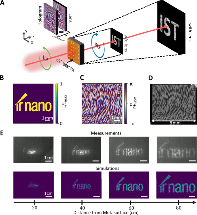
A Schematic sketch of combining the phase pattern of the hologram with the pattern of a magnifying lens to achieve enlarged imaging of the RCP holographic image. B Targeted far-field intensity pattern displaying the letters “ir nano” at 60 cm distance from the metasurface. C Calculated metasurface phase profile with the Gerchberg–Saxton algorithm according to the targeted intensity pattern superimposed with the phase profile of a magnifying lens. D Photograph of the 8 × 8 mm² metasurface written optically. E Measured and simulated intensity patterns at varied distances from the metasurface. The designed hologram is best visible 60 cm behind the metasurface.
In another experiment, a third functionality of a beam steerer is added to the magnified holography metasurface by superimposing the previous phase mask with the phase mask of a beam steerer (see Fig. 5A). The resulting metasurface deflects the enlarged hologram by a given angle of 10° as shown in Fig. 5B. For better visualization, the incident LCP light is not filtered out completely, leading to a point-like intensity pattern at 0°. This demonstrates the ability of combining several different functionalities within the same metasurface by simply superimposing the corresponding phase masks which is not possible with conventional optical elements.
Fig. 5: Multifunctionality and cascaded metasurfaces.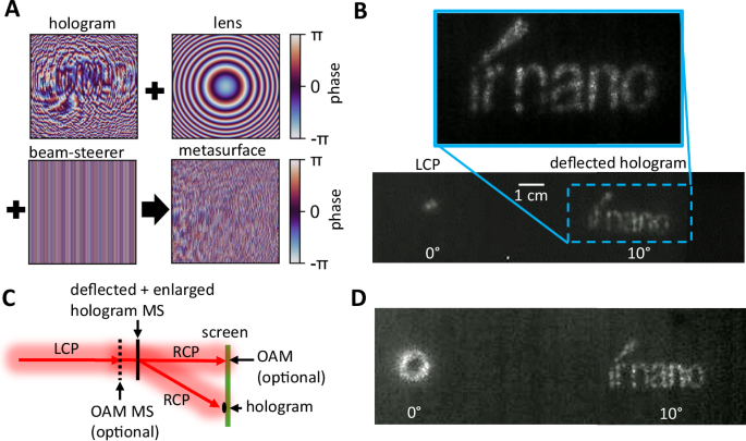
A Superimposed phase masks of the hologram, magnifying lens, and beam steerer leading to the phase mask of the metasurface for enlarged and deflected holography. B Measured intensity profiles of the corresponding metasurface. The incident LCP light is attenuated and visible at 0°, while the “ir nano” hologram appears deflected at 10°. C Sketch of the measurement setup for cascaded metasurfaces creating the OAM at 0° (optional) and the deflected and enlarged hologram at 10°. D Measured OAM intensity profile at 0° and deflected hologram at 10°.
Moreover, by cascading two metasurfaces the remaining unaffected incident polarized light can be reused for another functionality. This is possible because the converted RCP light from the first metasurface transmits unaffected through the second metasurface. A sketch of the setup and concept employed is shown in Fig. 5C by inserting another metasurface (black dotted line) into the beam path. The first metasurface employed corresponds to the OAM metasurface with l = 3, while the second metasurface features the deflected and enlarged hologram from Fig. 5A. The resulting intensity profiles at the screen are displayed in Fig. 5D. Here, the characteristic ring-pattern of the OAM appears at 0° and the deflected hologram at 10°. A second example of cascaded metasurfaces with two holograms is shown in Supplementary Note 9.
Finally, we design a hologram metasurface exhibiting two different holograms at different positions z1 and z2 from the metasurface with a diffractive neural network (see Supplementary Note 10)40,41. The phase of the scattered light is altered to not only display a hologram at a set distance, but also additionally enables the reordering of the light upon propagation to form a second hologram with a different intensity distribution. This concept is visualized in Fig. 6A. Here, at position z1, the hologram showing a distorted lattice representing the amorphous phase with the caption “aIST” is displayed. At a second position z2, the observable hologram changes to a periodic lattice representing the crystalline phase with the caption ‘cIST’. The calculated phase mask is shown in Fig. 6B. Notice that we took the actual beam shape of the laser into account to achieve homogeneous intensity distributions within the hologram images. Measurements performed with a Pyrocam IV by Ophir Photonics at 16 and 21 cm are shown in Fig. 6C. The observable pattern changes as designed upon increasing the distance. Numerical simulations (see Fig. 6D) are in good agreement with the experimental data. The evolution of the hologram by varying the distance behind the metasurface is shown in Supplementary Video 1.
Fig. 6: Dual-hologram.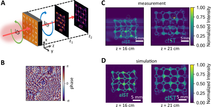
A Schematic sketch of the employed dual-holography concept. The IST metasurface leads to two different holograms at specific distances behind the metasurface. B Applied phase mask computed with a diffractive neural network. C Measurement of the holograms displaying “aIST” at z1 = 16 cm with a distorted lattice structure and “cIST” with a periodic lattice at z2 = 21 cm. D Numerical simulations clearly resolve the two holograms at different distances behind the metasurface.