
Experimental setup and magnetic properties
We have prepared two synthetic antiferromagnets with different degrees of magnetic compensation to identify the repercussions of long-range dipole interaction and DMI on the dynamics of the skyrmion tubes. The stack structures consist of Ta(5.00)/[Pt(1.00)/Ir(0.40)/FMB1/Pt(1.00)/Ir(0.40)/FMT1]×15/Pt(1.00) (numbers in nm) (ST1, hereafter), and Ta(5.00)/[Pt(1.00)/Ir(0.40)/FMB2/Pt(1.00)/Ir(0.40)/FMT2]×25/Pt(1.00) (ST2, hereafter), respectively, deposited on 100 nm-thick silicon nitride membrane substrates (see Table 1 for the detail). The FMB and FMT layers are addressed as a bottom (Co-rich) FM and top (Fe-rich) FM layer, respectively, and they are antiferromagnetically coupled via the Pt/Ir interlayers. As shown in Fig. 1a, the compensation ratio of the magnetic moments, mC = 1 − |mT + mB | /(|mT | + |mB | ), was determined to be approximately 50% (ST1) and 80% (ST2) using magnetometry where the mT and mB denote the magnetic moments of FMT multilayers and FMB multilayers, respectively. The local SyAFM configuration, formed by a pair of adjacent CoB and CoFeB layers separated by the metallic spacer (see Table 1), is repeated 15 times, respectively 25 times, to induce the skyrmion tube structure. Our magnetization measurement suggests that no local breakdown of the antiferromagnetic (AFM) coupling between the magnetic domains occurs42 in these stacks due to the sufficiently large interlayer exchange18 resulting from the presence of Ir43.
Table 1 Building blocks of the SyAFM multilayerFig. 1: Experimental setup, magnetization measurements, and element-specific detection of SyAFM skyrmion tubes.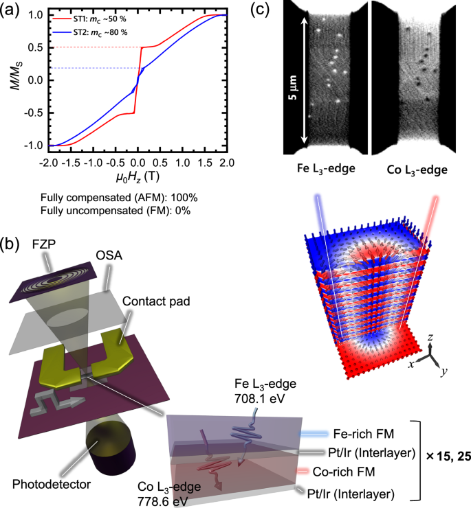
a Normalized out-of-plane M-HZ curves for ST1 (mC ≈ 50%) and ST2 (mC ≈ 80%). b A schematic of the scanning transmission X-ray microscopy (STXM) setup. FZP Fresnel zone plate, OSA order sorting aperture, FM ferromagnet. c Direct observation of SyAFM coupling of skyrmion tubes under perpendicular magnetic field μ0HZ = 130 mT at room temperature, and schematic of the spin structure of the SyAFM skyrmion tube.
To directly demonstrate the interlayer AFM coupling that leads to fully coupled skyrmions in the layers before and after pulse injection (see “Methods”), we employed an element-specific detection technique: scanning transmission X-ray microscopy (STXM) with magnetic circular dichroism as the contrast mechanism, as illustrated in Fig. 1b. Owing to the characteristics of X-rays, the absorption and magnetic response of each element becomes energy-dependent, clearly indicating the presence of antiferromagnetically coupled skyrmions in our systems, see Fig. 1c, as expected from the M-Hz curve. Since STXM is a transmission technique, note that the magnetic contrast is averaged across all layers containing the selected element. This confirms the presence of laterally and uniformly coupled skyrmions throughout the entire stack, which are described as skyrmion tubes. Figure 1c presents clear AFM skyrmion tubes using the L3-edges of Fe (708.1 eV) and Co (778.6 eV) for stack ST2. Additionally, we confirmed that all the skyrmion tubes retain their AFM coupling after multiple current pulses, which indicates that all the skyrmions in the layers are fully coupled before and after their current-induced motion (see Supplementary Note 1). Furthermore, all skyrmion tubes exhibit no discernible multilevel gray XMCD contrast, confirming that inhomogeneous skyrmionic textures such as skyrmionic cocoons or bobber-style terminated skyrmions are absent owing to strong interlayer exchange coupling.
It is well known that the skyrmion size affects the quantitative evolution of the Hall angle in the skyrmion Hall effect44,45,46,47. Hence, by applying out-of-plane magnetic fields, we adjusted the skyrmion size to a fixed diameter of ~100 nm for each sample. In the next section, we systematically investigate the current-induced dynamics of the SyAFM skyrmion tubes.
Current-induced dynamics of SyAFM skyrmion tubes
We first nucleate the skyrmion tubes by using a relatively high current density (J ≥ 15 × 1011 Am−2) under selected magnetic fields48 and measured the average skyrmion velocity and average skyrmion Hall angle for stacks of different compensation. The fact that the SyAFM skyrmion tube moves along the technical current direction indicates that the spin-orbit torque (SOT) is the primary driving source for the current-induced motion12,15,16,22,46,47. To uncover the intrinsic dynamics, we track the trajectories of multiple SyAFM skyrmion tubes and link the trajectories using the Python module TrackPy (see Supplementary Movie 1), and then we take full statistics with respect to the individual skyrmion velocity, υ, as can be seen in Fig. 2a, b. Figure 2c shows the current-density dependence of the average skyrmion velocity, υave, defined by the Gaussian peak of the statistics for each stack. We clearly find that the skyrmion tubes are more efficiently driven for ST2 due to the higher mC, which is consistent with previous work16. Note that υave is almost the same between the positive and negative pulses. Moreover, in Supplementary Movie 1, the SyAFM skyrmion tubes exhibit unambiguous diagonal motion, demonstrating a finite skyrmion Hall effect owing to the uncompensated magnetic moments between the top and bottom FM layers. We note that the absolute value of the skyrmion Hall angle depends on the size of the skyrmions and their domain wall width49: the skyrmion Hall angle inversely scales with the radius of the skyrmion for a given skyrmion domain wall width. To scrutinize the current-induced SyAFM skyrmion tube dynamics, we proceed by thoroughly investigating the skyrmion Hall effect.
Fig. 2: Current-induced motion of SyAFM skyrmion tubes.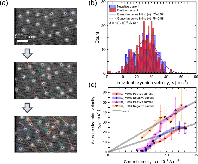
a Representative tracked trajectories of current-induced motion of SyAFM skyrmion tubes. b Statistical analysis of the individual SyAFM skyrmion tube velocity for the stack ST1 (mC = 50%) under μ0HZ = 70 mT at J = 13 × 1011 A m–2. Red and blue colors correspond to the positive and negative current polarity, respectively. The curves denote the Gaussian curve fitting. c The current-density dependence of the average velocity, υave, is defined by the Gaussian peak positions with ±1σ bars of the curve fitting in Fig. 2b. Red circles, blue rectangles, magenta triangles, and orange inverse triangles represent positive current polarity (ST1 stack), negative polarity (ST1 stack), positive polarity (ST2 stack), and negative polarity (ST2 stack), respectively. In line with literature, we use the common definition of the flow regime as the region in which the average skyrmion velocity exhibits a linear dependence on the applied current density.
Non-reciprocity in the skyrmion Hall effect for the low-compensation SyAFM skyrmion tubes
For a quantitative evaluation of the skyrmion Hall effect, we employed the same protocol as for the skyrmion velocity, where the averaged skyrmion Hall angle, θave, is extracted from the peak of the Gaussian fitting. Figure 3a presents the statistics of the skyrmion Hall angle for the skyrmion ensembles in the stack ST1 (mC = 50%). We find that the values of θave are reciprocal for both current pulse polarities at υave = 10 m s−1, which corresponds to the creep/depinning regime (see Fig. 2c). Surprisingly, we find an intriguing behavior for the higher velocity in the flow regime of υave = 25 m s−1, where the degeneracy of two Gaussian peaks regarding the current polarity is distinctly lifted, indicating the presence of a non-reciprocal skyrmion Hall effect in the flow regime (see also Supplementary Movies 1 and 2). To ascertain the physical origin of the non-reciprocity in the Hall angle, we move on to measure the average velocity dependence of θave. As depicted in Fig. 3b, the NSkHE is found to vanish in the creep/depinning regime, as anticipated from Fig. 3a. This implies that the intrinsic mechanism dominates over the pinning effects37 and is essential for the observed strong NSkHE. Intriguingly, the NSkHE becomes negligible for the high-compensation stack (ST2, mC = 80%), as it is evident from Fig. 3b. This dependence of the NSkHE on the degree of magnetic compensation unveils that the long-range dipole interaction, which is significant only for ST1, is one of the critical factors for tailoring the non-reciprocity.
Fig. 3: Dependence of the non-reciprocal skyrmion Hall effect on the degree of magnetic compensation.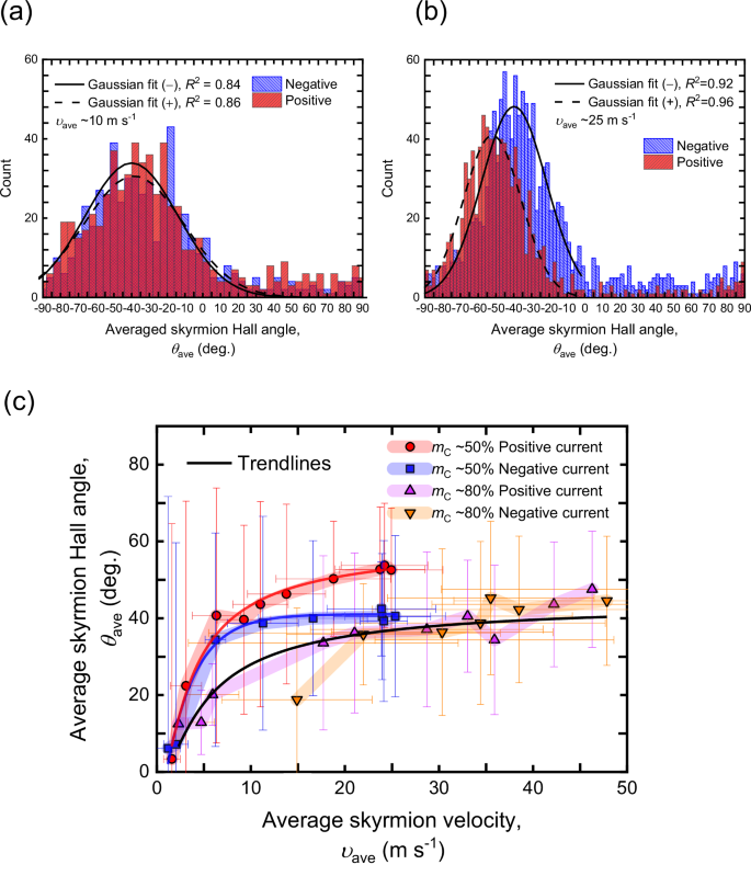
a Statistical analysis of the individual skyrmion Hall angle for the stack ST1 (mC = 50%) under μ0HZ = 70 mT at υave = 10 m s–2 and b 25 m s–2. c The average velocity dependence of θave with ±1σ bars of the curve fitting extracted from the Gaussian peaks in Fig. 3a. Red circles, blue rectangles, magenta triangles, and orange inverse triangles represent positive current polarity (ST1 stack), negative polarity (ST1 stack), positive polarity (ST2 stack), and negative polarity (ST2 stack), respectively.
Micromagnetic simulations and discussion
Next, we analyze the dynamics of the SyAFM skyrmion tubes, where reversing the direction of the applied current results in a different skyrmion Hall angle, indicating strongly non-reciprocal behavior. In ferromagnetic (FM) multilayers, long-range magnetic dipolar interactions facilitate the formation of hybrid chiral skyrmion tubes, which consist of Bloch-type skyrmions at the center of the tubes and Néel-type skyrmions of opposite chiralities at the surfaces40,41. These hybrid skyrmion tubes can exhibit a multifaceted response to SOTs50,51, leading to a rich tapestry of dynamic effects. However, such exotic hybrid chiral skyrmion dynamics have yet to be demonstrated experimentally. In particular, long-range dipolar interactions are predominant in the SyAFM system with substantial uncompensated moments, potentially acting as a stabilizing agent for the antiferromagnetically coupled hybrid skyrmion tube: the “hybridness” of the skyrmion tubes, defined as the ratio of Néel to Bloch components, can be modulated by adjusting the magnetic compensation ratio and the number of repetitions within the SyAFM multilayers, thus offering a means to control the dynamics of these skyrmions. To check this conjecture, we next employ micromagnetic simulations using the MuMax3 software52, with parameters extracted from experimental data as detailed in the “Methods” section.
The spin structure of the skyrmion tube obtained from relaxation at zero field using micromagnetic simulation provides further insights into the effect of magnetic compensation on the equilibrium structure. These simulations reveal that the skyrmion helicity varies across different layers due to net stray fields arising from the net magnetization in the multilayer system. Figure 4a illustrates the 2D spin profiles of individual layers of the SyAFM multilayer, indicating the orientation of magnetization: red for magnetization along the +x-axis and blue for the −x-axis. For the 80% compensated stack (ST2), the spin profiles show homochiral Néel-type skyrmion tubes throughout the multilayer stack, with each layer exhibiting a helicity shift of π due to the AFM coupling. In contrast, at 50% compensation, a Néel-type domain wall characterizes one end of the skyrmion tube with helicity (η) being zero, while the helicity varies continuously through successive layers, maintaining AFM alignment at their cores. The simulation also indicates that the hybrid character should have a subtle but finite Bloch component, which is evidenced by Lorentz transmission microscope imaging (TEM) (details, see Supplementary Note 2).
Fig. 4: Micromagnetic simulations of antiferromagnetic hybrid chiral skyrmion tubes.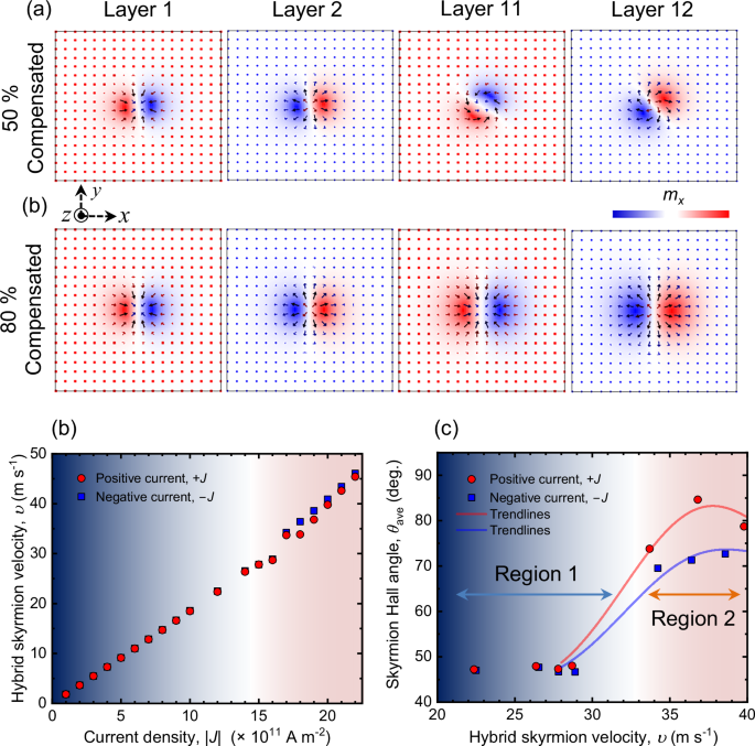
a Two-dimensional (2D) profiles of magnetic skyrmions in layers 1, 2, 11, and 12 for SyAFM systems with mC = 50% and mC = 80% compensation, respectively. Arrow directions indicate the magnetization orientation within each layer, while color variations denote the magnetization direction along the x-axis. For the mC = 80% compensated SyAFM system, the skyrmion helicity remains constant across all layers. In contrast, for the mC = 50% compensated SyAFM, the skyrmion helicity transitions from Néel to a hybrid type. b The velocity of hybrid skyrmions in the mC = 50% compensated SyAFM system, depicted as a function of the current density for two antiparallel in-plane (x-axis) current directions. c Variation of the skyrmion Hall angle for hybrid skyrmion tubes, as a function of skyrmion velocity for two antiparallel in-plane (x-axis) current directions, showcasing the non-reciprocal response of skyrmions to applied electrical currents at higher current density.
Figure 4b elucidates the velocity of hybrid chiral skyrmion tubes as a function of current density obtained via micromagnetic simulation (see “Methods” for details). Our results reveal that the velocity of the hybrid skyrmion tubes exhibits a near-linear response to the current density, paralleling the behavior in the experimental results, as depicted in Fig. 2c. Most importantly, Fig. 4c illustrates a distinct transition in skyrmion dynamics: within region 1, the skyrmion Hall angle remains reciprocal, indicating an absence of directional bias. However, beyond a critical velocity threshold of ~30 m s–1, defining the onset of region 2, there is a significant increase in the skyrmion Hall angle, with different amounts for opposite directional currents, resulting in a prominent non-reciprocal behavior.
Non-reciprocal dynamics have been reported for ferrimagnetic insulators with effective in-plane exchange bias37, where the shape distortion in the skyrmion configuration leads to a finite difference for the off-diagonal elements in the dissipation tensor due to asymmetric pinning effects37,53. The field-like torques (FLTs) also induce skyrmion shape distortions, possibly leading to an asymmetric skyrmion Hall angle46. Although the NSkHE could be induced via these scenarios, this is not the case for our stacks: First of all, when asymmetric pinning causes non-reciprocity, the NSkHE should emerge with a significant velocity difference even in the creep and depinning regimes via the shape or velocity-dependent skyrmion Hall effect22,44,45,46,47 as previously observed37,53. Secondly, our spin-torque ferromagnetic resonance (ST-FMR) measurements reveal comparably small FLT components compared to the damping-like torque (DLT) (see Supplementary Note 3). To substantiate the above discussion, we have investigated the shape distortions by computing the dissipation tensor, \({D}_{\mu \gamma }={\int }_{S}\,{d}^{2}{{{\bf{r}}}}\,\left({\partial }_{\mu }{{{{\bf{m}}}}}_{i}\bullet {\partial }_{\gamma }{{{{\bf{m}}}}}_{i}\right)\), for the SyAFM hybrid chiral skyrmion in the aforementioned regions (see Supplementary Note 4). Figure 5a, b illustrates the differences \({\widetilde{D}}_{\mu \gamma }=\,{D}_{\mu \gamma }\left[+J\right]-{D}_{\mu \gamma }\left[-J\right]\) of the lateral average of the dissipation tensor for two antiparallel directions of the applied current. At the skyrmion velocity of υ = 11 m s–1 (region 1), the tensor elements, \({\widetilde{D}}_{{xx}}\), \({\widetilde{D}}_{{xy}}\), \({\widetilde{D}}_{{yx}}\), and \({\widetilde{D}}_{{yy}}\), show no deviation, indicating that the skyrmion remains circular during its motion. At a higher velocity of υ = 34 m s–1 (region 2), the tensor elements change when the direction of the applied current is reversed. However, these imperceptible deviations are insufficient to cause the observed strong NSkHE. This certainly shows that shape distortions do not predominantly contribute to the non-reciprocity of the skyrmion Hall angle, which necessitates a different mechanism to describe our experimental observations.
Fig. 5: Evolution of both dissipation and SOT efficiency tensors (Dμγ and Iμγ, respectively) in two different regions of skyrmion dynamics.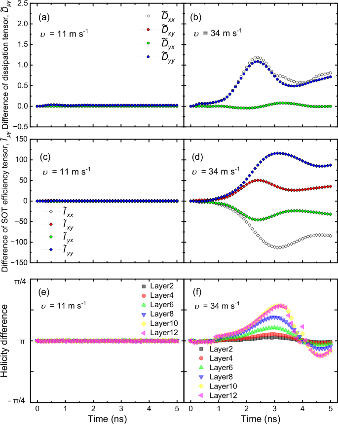
Difference of the dissipative tensors (layer-averaged) at the skyrmion tube velocity of a υ = 11 m s–1 and b 34 m s–1. Difference of the SOT efficiency tensors (layer-averaged) at the skyrmion tube velocity of c υ = 11 m s–1 and d 34 m s–1. The xx, xy, yx, and yy components correspond to white, red, green, and blue colors, respectively. Layer-dependent helicity difference between positive and negative pulses at the skyrmion tube velocity of e υ = 11 m s–1 and f 34 m s–1, illustrating the asymmetry that leads to non-reciprocity in the skyrmion Hall effect.
Here, we unravel the possible physical origin of the NSkHE for the SyAFM hybrid chiral skyrmion tube by computing the SOT efficiency tensor, \({I}_{\mu \gamma }={\int }_{S}\,{d}^{2}{{{\bf{r}}}}\,{[{\partial }_{\mu }{{{{\bf{m}}}}}_{i}{{{\boldsymbol{\times }}}}{{{{\bf{m}}}}}_{i}]}_{\gamma }\)(see Supplementary Note 4) in both regions of the skyrmion tube motion. Figure 5c, d shows the difference, \({\widetilde{I}}_{\mu \gamma }=\,{I}_{\mu \gamma }\left[+J\right]-{I}_{\mu \gamma }\left[-J\right]\), of the lateral average of the SOT tensor for two opposite directions of the applied currents: in region 1 (Fig. 5c), the \({\widetilde{I}}_{\mu \gamma }\) is negligibly small and comparable to the \({\widetilde{D}}_{\mu \gamma }\). However, in region 2 (Fig. 5d), it is at least two orders of magnitude higher than those of \({\widetilde{D}}_{\mu \gamma },\) therefore indicating that this is the main contribution leading to the non-reciprocity of the skyrmion Hall angle.
To clarify the mechanism for such a change in the SOT tensors, we further compute the variation of the average helicity of the hybrid skyrmion tubes during the current-induced dynamics. In region 1, the skyrmions retain their helicity during motion, which is unambiguously seen in Fig. 5e (also see Supplementary Movie 3 and 4), and thus the difference in the average of the Iμγ elements is negligible as expected. However, in region 2, layers with Néel-type characters change their helicity and acquire more of a Bloch-type character (see Supplementary Movie 5 and 6), causing the non-reciprocity in the skyrmion Hall angle as shown in Fig. 5f. The dynamical behavior of the skyrmion helicity is a key feature that warrants a detailed discussion. Our results indicate that the helicity transition from Néel to the Bloch type (namely helicity ranging from zero to π/2) occurs across the z-direction in region 2, where the current density is higher. This transition is more pronounced in magnetic layers where the skyrmion texture exhibits a Bloch character in equilibrium (see Supplementary Note 5). This non-uniform variation of the helicity across the layers is significant since the resultant oscillations in time in the values of the helicity cannot be treated as minor perturbations; on the contrary, they significantly alter the skyrmion dynamics, leading to the non-reciprocal Hall effect that we observe. Therefore, the dynamics of the hybrid-skyrmion helicity is a critical factor driving the observed non-reciprocity.
The transition in the helicity and its resulting impact on the skyrmion dynamics highlight the intricate interplay between magnetic interactions in SyAFM multilayers. This complexity is further compounded by dipolar interactions, that can be tuned by the level of compensation. Our findings show that these interactions are crucial for stabilizing the hybrid chiral skyrmion tubes and modulating their behavior under applied currents. Dipolar interactions, combined with the uncompensated magnetic moments, create a unique environment where skyrmion dynamics can be finely tuned by adjusting the magnetic compensation ratio and the number of repetitions within the multilayers.
We note that while the parameters used in the micromagnetic simulations are obtained experimentally (see “Methods” section), there are limitations to the quantitative analysis. For instance, the phenomenological damping obtained from our experiments has multiple contributions, including inhomogeneous broadening and interfacial spin mixing. Additionally, we are unable to experimentally distinguish the contribution of the Oersted field from the intrinsic symmetry of the FLT. These key factors would affect the quantitative agreement with the experimental observation. Also, since our micromagnetic calculations are done at zero temperature, we cannot expect a full quantitative agreement. Therefore, our calculations are used to provide the key qualitative explanations of the major features in the experimental observation. The unambiguous conclusion that we can draw is that the observed NSkHE without any extrinsic in-plane symmetry breaking highlights the critical role of the internal degree of freedom in the current-induced motion of the skyrmion tubes.