We investigated TaIrTe4/Fe3GaTe2 vdW heterostructures (Fig. 1a)19 due to their promising properties, anticipating that their combination could yield contemporary phenomena such as large non-linear Hall effects and unconventional spin-orbit torque (SOT) magnetization dynamics. TaIrTe4 is a vdW topological Weyl semimetal (WSM) candidate, with a significant Berry curvature dipole and large spin splitting of the electronic bands20. In addition, it provides unconventional charge-spin conversion with an out-of-plane spin polarization component that can induce an out-of-plane SOT18 on the adjacent PMA ferromagnet to induce a magnetic field-free switching. On the other hand, Fe3GaTe2 is a unique vdW topological nodal line metallic ferromagnet with strong PMA above room temperature with Tc around 370 K10. We fabricated Hall-bar devices based on TaIrTe4/Fe3GaTe2 vdW heterostructures, along with individual Hall bars on TaIrTe4 and Fe3GaTe2 crystals, to characterize properties, such as the anomalous Hall effect (AHE), 2nd harmonics measurements and SOT-driven switching experiments (details in Methods section and Supplementary Fig. S1). Figure 1b presents a typical optical microscope image of a representative TaIrTe4/Fe3GaTe2 Hall-bar device.
Fig. 1: Van der Waals heterostructure of TaIrTe4/Fe3GaTe2 and harmonic measurements on TaIrTe4.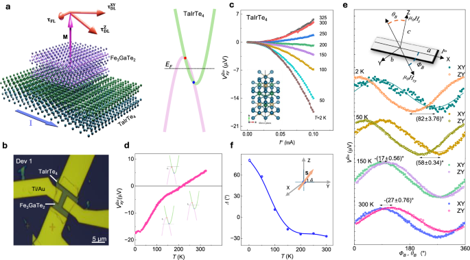
a Schematic diagram of a van der Waals (vdW) heterostructure of Weyl semimetal TaIrTe4 and out-of-plane ferromagnet Fe3GaTe2. Band structure of typical type-II Weyl semimetal with two Weyl nodes. b Optical image of representative TaIrTe4/Fe3GaTe2 vdW heterostructure Hall bar device with a scale bar of 5 µm. c 2nd harmonic transverse Hall voltage \({V}_{{xy}}^{2\omega }\) in response to an applied alternating current \({I}^{\omega }\) along a-axis at different temperatures for a device with 20 nm thin TaIrTe4. The inset illustrates the crystal structure of Td-TaIrTe4, characterized by low crystal symmetry and a mirror plane along the crystallographic b-axis. d 2nd harmonic transverse Hall voltage \({V}_{{xy}}^{2\omega }\) with temperature at an \({I}^{\omega }\) of 0.1 mA of TaIrTe4. Insets show the energy dispersion curve of type-II Weyl semimetal and tuning of Fermi level energy (EF) with temperature. e 2nd harmonic voltage \({V}^{2\omega }\) response measured in TaIrTe4 device as a function of angle between current applied along a-axis of TaIrTe4 (|\({I}^{\omega }\) | = 0.1 mA) and external magnetic field (13 T). The device is rotated in XY and ZY planes, as depicted in the schematics. In the XY rotation, the device rotates such that the magnetic field aligns parallel to the sample surface and making \({\varPhi }_{B}\) angle with a-axis of TaIrTe4, whereas in ZY rotation, the device rotation changes magnetic field direction from a-axis of TaIrTe4 to c axis and making \({\theta }_{B}\) angle with c-axis with TaIrTe4. The solid lines are the fits. f Temperature dependence of shift (Δ) in the maxima or minima of \({V}^{2\omega }\) vs ΦB and θB curves. This shift is denoted as out-of-plane canting angles, as illustrated in schematics. Such shift is directly correlated to the out-of-plane spin canting angle, which is estimated to be − (27\(\pm\)0.76)° at room temperature. Error bars in f are obtained by fitting experimental data in e using sinΦB and sin(θB + Δ) functions.
Tunable spin texture using bilinear magnetoresistance and 2nd harmonic Hall effect in TaIrTe4
TaIrTe4 exhibited a strong nonlinear Hall effect, characterized by a 2nd harmonic Hall voltage that nonlinearly depends on driving currents sourced along the a-axis of the crystal, perpendicular to its mirror plane at room temperature (Fig. 1c). Unlike linear Hall effects observed in systems with broken time-reversal symmetry, the nonlinear Hall effect in TaIrTe4 arises from the large Berry curvature dipole in the absence of inversion-symmetry (also see Supplementary Note 2). Notably, the nonlinear Hall voltage changed sign near ~200 K (Fig. 1c, d), indicating temperature-induced shift in the chemical potential, consistent with the Weyl semi-metallic properties of TaIrTe421. The current induced spin polarization in TaIrTe4 are probed using bilinear magnetoelectric resistance (BMER) technique9,22, measuring 2nd harmonic voltage while rotating the samples in XY and ZY planes (Fig. 1e). In XY rotation, the magnetic field vector remains in the ab crystallographic plane sweeping azimuthal angle (ΦB) with respect to the a-axis of TaIrTe4, whereas in ZY rotation, the field vector sweeps polar angle (θB) with respect to the c-axis of TaIrTe4 in the ac plane. Figure 1e depicts the temperature dependence of 2nd harmonic voltage with ΦB and θB. The direction of resultant spin angular momentum arises due to CSC effects in TaIrTe4 being equivalent to angular shift (Δ) of BMER curves measured along XY and ZY geometries. The Δ is found to be \(-\)(\(27\pm 0.76\))° at room temperature, indicating the presence of an out-of-plane spin density induced in TaIrTe4. Such spin-polarization can help in generating unconventional out-of-plane SOT in adjacent ferromagnetic layer Fe3GaTe2 with PMA resulting in field-free deterministic switching. The temperature dependence of Δ (Fig. 1f) suggests that the polarity and magnitude of the spin canting angle in TaIrTe4 are highly tunable by the position of chemical potential/Fermi level9.
Perpendicular magnetic anisotropy of Fe3GaTe2
To verify the magnetic property and anisotropy of Fe3GaTe2, the anomalous Hall resistance Rxy is measured at different temperatures ranging from 2 to 300 K (Fig. 2a, b). A square-shaped magnetic hysteresis loop is observed with coercivity around 100 mT and anomalous Hall resistance (RAHE) of around 1.5 Ω at room temperature, where the latter is directly proportional to saturation magnetization (Ms) of Fe3GaTe2. The RAHE vs T curve, shown in Fig. 2c, is fitted with \({R}_{{xy}}\left(T\right)={R}_{{xy}}\left(0\right){\left(1-{\left(\frac{T}{{T}_{c}}\right)}^{2}\right)}^{\beta }\) analogues to Bloch equation for magnetization vs temperature curve to estimate Curie temperature (\({T}_{c}\) = \(369.14\pm 7.73{{{\rm{K}}}}\))10 and critical magnetization exponent \(\beta=0.35\,\)22,23,24,25,26. Figure 2d shows the anomalous Hall resistance of Fe3GaTe2 as a function of in-plane magnetic fields at different temperatures from 2 to 300 K. A magnetic hysteresis loop is observed at all temperatures, with finite remanence and coercivity, consistent with the typical behavior of PMA magnets along their hard axis (Fig. 2e).
Fig. 2: Magneto-transport characterization of Fe3GaTe2.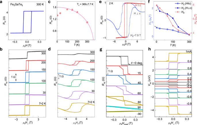
a, b Anomalous Hall resistance of Fe3GaTe2 as a function of out-of-plane magnetic fields at 300 K and temperature dependence ranging from 2 to 300 K. c Anomalous Hall amplitude at the saturated field as a function of temperature. Solid line is fit to extract the Curie temperature (\({T}_{c}=369.14\pm 7.73{{{\rm{K}}}}\)) d Anomalous Hall resistance of Fe3GaTe2 as a function of in-plane magnetic fields at different temperatures ranging from 2 to 300 K. e Comparison of anomalous Hall effect measurement for field swept parallel to sample plane (i.e., \(H{{{\perp }}}c\)) vs perpendicular (i.e., \({H||c}\)) to sample plane at 2 K temperature. The anisotropic field (HK) is ~7.9 T, indicating strong perpendicular magnetic anisotropy present in Fe3GaTe2. f Variation of coercive fields and anisotropic fields with temperature extracted from (\({R}_{{xy}}\) vs \({\mu }_{0}{H}_{{{{\perp }}}}\)) and (\({R}_{{xy}}\) vs \({\mu }_{0}{H}_{{||}}\)) measurements. g AHE signals \({R}_{{xy}}\) with different out-of-plane angles (θ) between the magnetic field and the c-axis of the sample plane at 300 K. h Variation of AHE signals \({R}_{{xy}}\) with positive and negative DC bias currents.
Figure 2f shows the variation of magnetic coercivity (Hc) in both field directions (i.e., \(H\, {{\perp }}\, c-axis\) and \({H||}c-axis\)) and anisotropic field with temperature. The anisotropic field (HK), defined as the difference in saturation between in-plane and out-of-plane magnetic fields, reaches ~7.9 T at 2 K and ~3.8 T at 300 K. Such a high value of HK suggests that Fe3GaTe2 has a very high magnetic anisotropy energy density with a very strong PMA. The coercive field (Hc) is also quite high along in-plane direction as compared to out-of-plane direction. Both the Hc and HK decrease with an increase in temperature approaching the Curie temperature of Fe3GaTe2. Figure 2g illustrates AHE signals Rxy measured at varying out-of-plane angles (θ) between c-axis of sample and magnetic field. It can be noted here that the magnitude of AHE signal (\({R}_{{xy}}^{{AHE}}=\frac{{R}_{{xy}}\left(+{H}_{S}\right)-{R}_{{xy}}\left(-{H}_{S}\right)}{2}\)) remains almost constant till \(\pm {80}\)°; beyond that AHE loop disappears between \(\pm 600\,{{{\rm{mT}}}}\) field range. Again, this indicates a strong out-of-plane magnetic anisotropy present in Fe3GaTe2. Figure 2h shows the variation of AHE signals Rxy with positive and negative DC bias currents. We observed that the magnitude of anomalous Hall signal, the coercivity and saturation fields remain unchanged with positive or negative current bias varied from \(\pm 0.1 \;{{\rm{mA}}}\; {{\rm{to}}} \pm 1 \; {{\rm{mA}}}\), indicating the robustness of perpendicular anisotropic magnetic moment against dc current within these bias ranges.
2nd harmonic nonlinear Hall effect and spin-orbit torque induced magnetization dynamics in TaIrTe4/Fe3GaTe2 heterostructures
The harmonic Hall measurements are performed on TaIrTe4/Fe3GaTe2 heterostructures to quantitatively evaluate the non-linear effects and magnetization dynamics driven by SOT. When a sinusoidal current (\({I}^{\omega }\)) is applied to the vdW heterostructure, composed of the spin-orbit material TaIrTe4 and a ferromagnet Fe3GaTe2, spin-orbit torques \(({{{\boldsymbol{\tau}} }}_{{{\bf{SOT}}}})\) are exerted on the magnetization (m) of the Fe3GaTe2. This effect originates from the spin accumulation at the vdW interface due to efficient CSC in TaIrTe4. Typically, two mutually orthogonal torques are generated: the damping-like torque (\({{{{\boldsymbol{\tau }}}}}_{{{{\bf{DL}}}}} \sim {{{\bf{m}}}}{{\times }}({{{\boldsymbol{\sigma }}}}{{\times }}{{{\bf{m}}}})\)) and the field-like torque (\({{{{\boldsymbol{\tau }}}}}_{{{{\bf{FL}}}}}\,{{{\boldsymbol{ \sim }}}}\,{{{\boldsymbol{\sigma }}}}\times {{{\bf{m}}}}\))13,27.
In these measurements, applying a sinusoidal current (\({I}^{\omega }\)) with a fixed frequency of 213.3 Hz induces SOT-driven magnetization oscillation, generating harmonics in both the longitudinal and transverse resistance signals. The 1st and 2nd harmonic signals are measured and analyzed across various angles (\({\varPhi }_{B}\)) between the in-plane magnetic field (\(H{{{\perp }}}c\)) and the applied sinusoidal current (\({I}^{\omega }\)), as well as under varying external magnetic fields (\({H}_{{ext}}\)). This analysis provides information about the current-induced effective SOT fields and torques.
Since the spin Hall effect (SHE) in TaIrTe4 induces both in-plane and out-of-plane spin polarizations (\({\sigma }^{X,Y,Z}\)), the applied \({I}^{\omega }\) along the a-axis of TaIrTe4 generates corresponding components of the damping-like (\({{{{\boldsymbol{\tau }}}}}_{{{{\bf{DL}}}}}^{{{{\bf{X}}}},{{{\bf{Y}}}},{{{\bf{Z}}}}}\)) and field-like (\({{{{\boldsymbol{\tau }}}}}_{{{{\bf{FL}}}}}^{{{{\bf{X}}}},{{{\bf{Y}}}},{{{\bf{Z}}}}}\)) torques. The 2nd harmonic transverse voltage generated from these current-induced effective SOT fields componenets (\({H}_{{DL}}^{X,Y,Z},{H}_{{FL}}^{X,Y,Z}\)) and torques (\({{{{\boldsymbol{\tau }}}}}_{{{{\bf{DL}}}}}^{{{{\bf{X}}}},{{{\bf{Y}}}},{{{\bf{Z}}}}},{{{{\boldsymbol{\tau }}}}}_{{{{\bf{FL}}}}}^{{{{\bf{X}}}},{{{\bf{Y}}}},{{{\bf{Z}}}}}\)) in PMA ferromagnets is expressed as28,29,
$${V}_{{xy}}^{2\omega }= {V}_{{DL}}^{Y}\cos {\varPhi }_{B}+{V}_{{DL}}^{X}\sin {\varPhi }_{B}+{V}_{{DL}}^{Z}\cos 2{\varPhi }_{B}+{V}_{{FL}}^{Y}\cos {\varPhi }_{B}\cos {2\varPhi }_{B} \\ +{V}_{{FL}}^{X}\sin {\varPhi }_{B}\cos {2\varPhi }_{B}+{V}_{{FL}}^{Z}$$
(1)
Here, damping-like torque components generated by X, Y and Z spin polarization contribute to coefficients \({V}_{{DL}}^{X,Y,Z}\), and the field-like torque counterparts give rise to coefficients \({V}_{{FL}}^{X,Y,Z}\). The estimation of SOT fields (\({H}_{{DL}}^{X,Y,Z},{H}_{{FL}}^{X,Y,Z}\)) from coefficients (\({V}_{{DL}}^{X,Y,Z},{V}_{{FL}}^{X,Y,Z}\)) is detailed in Supplementary Note 7 (Supplementary Eqs. S1–S7).
$${V}_{{xy}}^{2\omega }={V}_{{DL}}\cos {\varPhi }_{B}+{{{{\rm{V}}}}}_{{{{\rm{FL}}}}}\cos {\varPhi }_{B}\cos {2\varPhi }_{B}$$
(2)
The 2nd harmonic Hall signal as a function of \({\varPhi }_{B}\) at constant fields (H > HK) is plotted in Fig. 3b. The \({V}_{{xy}}^{2\omega }\) vs \({\varPhi }_{B}\) curve is fitted with Eq. 2 to estimate SOT in materials containing only conventional in-plane spins30,31. However, \({V}_{{xy}}^{2\omega }\) vs \({\varPhi }_{B}\) curve of TaIrTe4/Fe3GaTe2 could not be well fitted with Eq. 2 (see Fig. 3b). For proper fitting, we need to include \({V}_{{DL}}\cos {2\varPhi }_{B}\) and \({V}_{{DL}}\sin {\varPhi }_{B}\) terms as in Eq. 1, which consider additional torque components due to current-induced out-of-plane spin canting in TaIrTe4. The coefficients \({{V}_{{xy}}^{2\omega }}_{\cos {\Phi }_{B}}\), \({{V}_{{xy}}^{2\omega }}_{\sin {\Phi }_{B}}\) and \({{V}_{{xy}}^{2\omega }}_{\cos {2\Phi }_{B}}\) are hyperbolic functions of the magnetic field (see Supplementary Note 7, Eqs S2–S4), implying linear function on 1/(H-HK) or 1/H. The values of these coefficients were extracted by fitting the experimental 2nd harmonic transverse voltage and plotted in Fig. 3c-e. From these slopes, \({H}_{{DL}}^{X,Y,Z}\) are estimated (using RAHE = 1 Ω and RPHE = 0.0113 Ω; see Supplementary Note 6) and plotted as a function of current densities Ja.c. in Fig. 3g. The slope of \({H}_{{DL}}^{X,Y,Z}\) vs \({J}_{a.c.}\) are found out to be \({H}_{{DL}}^{X}/{J}_{a.c.} \sim \left(3.09 \pm 0.37\right)\times {10}^{-12}\;{{{\rm{T}}}}{{{{\rm{A}}}}}^{-1}{{{{\rm{m}}}}}^{2}\), \({H}_{{DL}}^{Y}/{J}_{a.c.} \sim \left(2.43\pm 0.15\right)\times {10}^{-12}\;{{{\rm{T}}}}{{{{\rm{A}}}}}^{-1}{{{{\rm{m}}}}}^{2}\) and \({H}_{{DL}}^{Z}/{J}_{a.c.} \sim \left(6.78\pm 0.44\right)\times {10}^{-12}\;{{{\rm{T}}}}{{{{\rm{A}}}}}^{-1}{{{{\rm{m}}}}}^{2}\). This analysis indicates that current-induced effective SOT fields or torques in TaIrTe4/Fe3GaTe2 heterostructure originated from the out-of-plane spin polarization \(({\sigma }^{Z})\), and it is larger than its in-plane counterparts \(({\sigma }^{{XY}})\).
Fig. 3: Angle-dependent harmonic Hall measurements in TaIrTe4/Fe3GaTe2 heterostructure.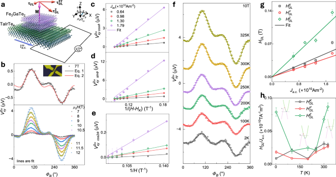
a Schematic of the TaIrTe4/Fe3GaTe2 heterostructure, illustrating the effects of damping-like torques (\({{{{\boldsymbol{\tau }}}}}_{{{{\bf{DL}}}}}^{{{{\bf{XY}}}}}\) and \({{{{\boldsymbol{\tau }}}}}_{{{{\bf{DL}}}}}^{{{{\bf{Z}}}}}\)) and field-like torques (\({{{{\boldsymbol{\tau }}}}}_{{{{\bf{FL}}}}}\)) on Fe₃GaTe₂ magnetization when the current is applied along the a-axis of TaIrTe₄ layer19. The 2nd harmonics Hall voltage (\({V}_{{xy}}^{2\omega }\)) measurement scheme is shown with an external in-plane magnetic field at angle ΦB relative to the a.c. current direction Iac. b \({V}_{{xy}}^{2\omega }\) vs ΦB of Dev1 at magnetic field 7 T and temperature 300 K. The solid lines are fitted with Eqs. 1 and 2. The second panel shows \({V}_{{xy}}^{2\omega }\) vs ΦB for varied magnetic fields (7-12 T). c–e Coefficient \({{V}_{{xy}}^{2\omega }}_{\cos {\varPhi }_{B}}\)(\(\cos {\varPhi }_{B}\) dependent in \({V}_{{xy}}^{2\omega }\)), \({{V}_{{xy}}^{2\omega }}_{\sin {\varPhi }_{B}}\)(\(\sin {\varPhi }_{B}\) dependent in \({V}_{{xy}}^{2\omega }\)) and \({{V}_{{xy}}^{2\omega }}_{\cos 2{\varPhi }_{B}}\)(\(\cos {2{\phi }}_{B}\) dependent in Vxy2ω) as a function of 1/(H-Hk) and 1/H under different current densities Ja.c.. The error bar in c, d and e are obtained from fitting of experimental data in (b) using Eq. 1. f Angle sweep of \({V}_{{xy}}^{2\omega }\) at different temperatures (2–325 K) at a constant magnetic field of 10 T. Solid lines are fit to experimental data using Eq. 1. g Damping-like field components (\({H}_{{DL}}^{X},{{H}_{{DL}}^{Y},H}_{{DL}}^{Z}\)) as a function of current density, with linear fits estimating HDL/ Ja.c., whereas error are obtained from the linear fit of c, d and e data. h Temperature dependence of HDL/ Ja.c. for TaIrTe4/Fe3GaTe2 device. Insets show the energy dispersion curve of type-II Weyl semimetal and tuning of Fermi level energy (EF) with temperature. The error bars in (h) are obtained by fitting experimental data in (f) using Eq. 1.
Tunable spin-orbit torque with temperature due to Fermi level tuning of TaIrTe4
The polarity and magnitude of spin accumulation generated by TaIrTe4 are influenced by the chemical potential9, resulting in temperature dependence changes in the tilt angle (as shown in Fig. 1f). A similar trend is expected in the current-induced effective SOT fields or torques. Hence, to observe the temperature dependence of SOT efficiency from the 2nd harmonic Hall signal of TaIrTe4/Fe3GaTe2, angle sweep second harmonic Hall (SHH) measurements are conducted at different temperatures. Figure 3f illustrates the \({V}_{{xy}}^{2\omega }\) vs \({\varPhi }_{B}\) curve at 10 T across different temperatures. Damping-like SOT effective fields (\({H}_{{DL}}^{X,Y,Z}\)) are estimated using Eq. 1. \({H}_{{DL}}^{Z}/{J}_{a.c.}\) is highly tunable with temperature (Fig. 3h), it decreased from 2 K to 100 K, reached a minimum between 100–200 K, and increased from 200 K to 325 K. This behavior aligns with the temperature dependence of current-induced spin accumulation (Fig. 1f), showing large out-of-plane spin polarization at 2 K and room temperature with a minimum near 100 K. Hence, the out-of-plane damping-like torque is observed to be tunable by the chemical potential of TaIrTe4.
Field-dependent harmonic Hall measurements
To further validate and estimate SOT components, we measured the 1st and 2nd harmonic transverse Hall resistance Rxy signal as a function of magnetic field applied parallel to the sample surface (\(H{{{\perp }}}c\)) and perpendicular to the applied current direction. In the 1st harmonic \({R}_{{xy}}^{{{{\rm{\omega }}}}}\) vs H, a hysteresis loop with a magnetic anisotropic field \({H}_{K}\) of ~ 1.5 T is observed (Fig. 4a). The 2nd harmonics transverse Hall resistance signal \({R}_{{xy}}^{2\omega }\) varied with the external magnetic field applied parallel to the sample surface. The measurements are conducted with the field oriented either perpendicular (\({H}_{y},{\varPhi }_{B}=90^\circ \; {or}\;270^\circ\)) or parallel (\({H}_{x},{\varPhi }_{B}=0^\circ\) or 180°) to the direction of current (or a-axis of TaIrTe4). These results are displayed in Fig. 4b, c. The resistance exhibited a hyperbolic dependence on the field for |H | >Hk, however became discontinuous for \({|H|} .
Fig. 4: Field-dependent harmonic Hall measurements in TaIrTe4/Fe3GaTe2 heterostructure.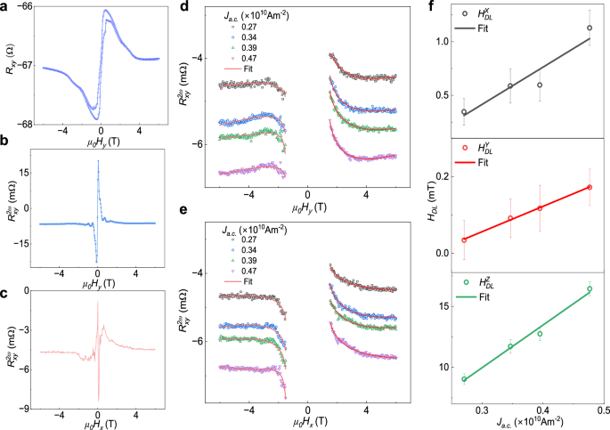
a 1st harmonic transverse resistance (\({R}_{{xy}}^{1\omega }\)) as a function of magnetic field swept parallel to the sample surface (\(H{{{\perp }}}c\)) and perpendicular to current direction, measured at 300 K on Dev 2. b, c 2nd harmonic transverse resistance \({R}_{{xy}}^{2\omega }\) varied as a function of the external magnetic field applied along parallel to the sample surface, with \({H}_{y}\) representing \(H{{{\perp }}}c\) and perpendicular to the current (\(H{{{\perp }}}{J}_{a.c.}\)), and \({H}_{x}\) representing \(H{{{\perp }}}c\) and parallel to the current (\({H||{J}_{a.c.}}\)). d, e Dependence of the 2nd harmonic transverse resistance \(({R}_{{xy}}^{2\omega })\) on the in-plane magnetic field (\({H}_{y}\) and \({H}_{x}\)) for different magnitudes of constant write current density ( Ja.c.). The data is fitted using equations simplified from Supplementary Eq S1–S7 (also see Supplementary Eq. S8–S9 and Supplementary Note 8). f Extracted effective damping-like field components (\({H}_{{DL}}^{X,Y,Z}\)) corresponding to spin polarization (\({{{{\boldsymbol{\sigma }}}}}^{{{{\bf{X}}}}},{{{{\boldsymbol{\sigma }}}}}^{{{{\bf{Y}}}}},{{{{\boldsymbol{\sigma }}}}}^{{{{\bf{Z}}}}}\)) as a function of Ja.c. along with corresponding error bars are obtained from fits to the 2nd harmonic signal.
Figure 4d, e shows 2nd harmonics transverse resistance \(({R}_{{xy}}^{2\omega })\) versus \({H}_{y}\) and \({H}_{x}\) for different applied sinusoidal current densities (\({J}_{a.c.}\)). The hyperbolic curvature of these plots sharpens with increasing current density. For \({R}_{{xy}}^{2\omega }\) vs \({H}_{y}\) data at \({\varPhi }_{B}=90^\circ\) and \(270^\circ\), Eq. (1) reveals that only x and z components of the SOT fields contribute to the 2nd harmonics signal (see Supplementary Eq. S8). Therefore, from the analysis of \({R}_{{xy}}^{2\omega }\) vs \({H}_{y}\) data at \({\varPhi }_{B}=90^\circ\), we have calculated \({H}_{{DL}}^{X},\) \({H}_{{DL}}^{Z}\), \({H}_{{FL}}^{X}\) and \({H}_{{FL}}^{Z}\). Similarly, for \({R}_{{xy}}^{2\omega }\) vs \({H}_{x}\) data (\({\varPhi }_{B}=0^\circ\)) and using the extracted \({H}_{{DL}}^{Z}\) and \({H}_{{FL}}^{Z}\) values, we have estimated \({H}_{{DL}}^{Y}\) and \({H}_{{FL}}^{Y}\) (see Supplementary Eq. S9 and also see Supplementary Note 6 and 8). The extracted values of \({H}_{{DL}}^{X,Y,Z}\) with different current densities \({J}_{a.c.}\) are plotted in Fig. 4f. The slopes of HDL vs \({J}_{a.c.}\) are found to be: \({H}_{{DL}}^{X}/{J}_{a.c.} \sim (0.348\pm 0.081)\times {10}^{-12}{{{\rm{T}}}} {{{{\rm{A}}}}}^{-1}{{{{\rm{m}}}}}^{2}\), \({H}_{{DL}}^{Y}/{J}_{a.c.} \sim (0.061\pm 0.002)\times {10}^{-12}{{{\rm{T}}}}{{{{\rm{A}}}}}^{-1}{{{{\rm{m}}}}}^{2}\) and \({H}_{{DL}}^{Z}/{J}_{a.c.} \sim (3.50\pm 0.27)\times {10}^{-12}{{{\rm{T}}}}{{{{\rm{A}}}}}^{-1}{{{{\rm{m}}}}}^{2}\). These findings also confirm that effective damping like the field corresponding to Z spin polarization is significantly larger than that from XY polarized spins.
It should be noted that TaIrTe4 alone also exhibits a 2nd harmonic voltage signal as function of \({\varPhi }_{B}\), arising from broken mirror symmetry and finite Berry curvature dipole. This signal follows a \(\cos {\varPhi }_{B}\) or \(\sin {\varPhi }_{B}\) dependence (Fig. 1e). So, the \({H}_{{DL}}^{X}\) and \({H}_{{DL}}^{Y}\) values from the fitting of \({V}_{{xy}}^{2\omega }\) vs \({\varPhi }_{B}\) data can be overestimated (Eq. 1). However, the estimation of Z-component damping-like field \({H}_{{FL}}^{Z}\) using coefficient \({{V}_{{xy}}^{2\omega }}_{\cos 2{\varPhi }_{B}}\) (Eq. 1), central to the conclusion of second harmonic measurements, remains consistent. Furthermore, only TaIrTe4 also has a unique field dependence of 2nd harmonics signal as shown in Supplementary Fig. S6d, which is quite different from SOT-induced \({R}_{{xy}}^{2\omega }\) vs H curve (see Fig. 4b–e). At large magnetic field, the \({R}_{{xy}}^{2\omega }\) vs H curve from TaIrTe4 appears to be linear function of magnetic field; hence, to account for the 2nd harmonics field contribution of TaIrTe4 and thermal effects31,32, a linear polynomial term is included while fitting the field-dependent curves (also see Supplementary Note 8). Also, the field-like torque for Dev 1 and 2 and Nerst effect voltages for Dev1 are shown in Supplementary Fig. S7 and Supplementary Note 7.
Field-free deterministic spin-orbit torque switching in TaIrTe4/Fe3GaTe2 heterostructure
SOT magnetization switching experiments are crucial for investigating magnetization switching characteristics, such as determining the critical switching current density, assessing the need for an external field to aid in switching, and identifying whether the process is deterministic or non-deterministic. A series of pulse currents (Ipulse) applied along the a-axis in the TaIrTe4/Fe3GaTe2 heterostructure can induce an unconventional spin current along the z-axis, with spin polarization \({\sigma }^{Z}\) oriented along the z-axis in TaIrTe49. This spin current generates an unconventional SOT on Fe3GaTe2, consisting of both field-like (τFL) and damping-like (τDL) torques, facilitating the switching of the magnetization direction M. The field-like torque τFL ~ \({{{\boldsymbol{\sigma }}}}\times {{{\bf{m}}}}\) induces the precession of M around the exchange field generated by spin polarization, while the damping-like torque τDL ~ \({{{\bf{m}}}}\times ({{{\boldsymbol{\sigma }}}}\times {{{\bf{m}}}})\) aligns M with the spin polarization \({{{\boldsymbol{\sigma }}}}\), predominantly driving the magnetization switching (Fig. 5a)33. Figure 5b shows the AHE at 300 K of Dev3 used for switching experiments. Figure 5c presents SOT-induced magnetization switching, measured by applying a pulsed write current (Ip) along the a-axis with a pulse duration of 50 ms. This is followed by a small D.C. read current (Ir~500 μA) to determine the magnetization state via the Hall resistance Rxy=Vxy/Ir. Due to a large unconventional SOT, fully deterministic field-free magnetization switching could be observed at room temperature with Ip = ±3.5 mA. Since the signal Rxy is proportional to the out-of-plane magnetization Mz, the SOT Rxy signal indicates a current-induced magnetization change between +Mz and -Mz. Notably, deterministic SOT switching of TaIrTe4/Fe3GaTe2 heterostructure is observed at Hx = 0 T, which indicates the creation of \({\sigma }^{Z}\) spin polarization in TaIrTe4 leading to an out-of-plane SOT component. The magnitude of the switching signal is comparable to the AHE signal magnitude with field sweep, showing a full magnetization switching34,35,36,37.
Fig. 5: Energy-efficient, field-free deterministic magnetization switching by spin-orbit torque in the TaIrTe4/Fe3GaTe2 heterostructure at room temperature.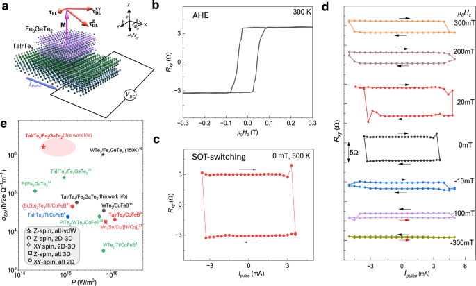
a Diagrammatic representation of TaIrTe4/Fe3GaTe2 heterostructure. This configuration leads to a significant out-of-plane antidamping torque (\({\tau }_{{AD}}^{{OOP}}\)), which is symmetric with respect to the current direction, facilitating field-free deterministic switching of the Fe3GaTe2 magnetization19. b AHE of the TaIrTe4/Fe3GaTe2 heterostructure device 3 with magnetic field sweep at 300 K. c Field-free full deterministic switching achieved at 3.5 mA pulse current and 500 µA current is used as reading current to measure magnetization states keeping external field zero at 300 K temperature. The current is applied along the symmetry axis (a-axis) of TaIrTe4. d Current-driven magnetization switching of TaIrTe4/Fe3GaTe2 under different bias fields parallel to the sample surface and current (Hx). The forward and backward current sweeps are distinguished by arrows. The data is vertically shifted to avoid overlap. e The benchmark of SOT spin Hall conductivity vs. power consumption with state-of-the-art results8,9,16,28,31,34,35,36,37. Ellipse represents error and device to device variation in the calculated parameters.
We further investigated the impact of deterministic SOT switching on the external in-plane magnetic field parallel to the current direction (Fig. 5d). The external in-plane magnetic field (Hx) can break the symmetry of deterministic SOT switching. As the strength of Hx increases, the switching mechanism transitions from being predominantly driven by the out-of-plane spin torque component (\({{{{\boldsymbol{\tau }}}}}_{{{{\bf{DL}}}}}^{{{{\bf{z}}}}}\)) to being influenced by the in-plane components \(({{{{\boldsymbol{\tau }}}}}_{{{{\bf{DL}}}}}^{{{{\bf{x}}}},{{{\bf{y}}}}})\). We observed that a small positive Hx has minimal effect on the SOT switching signal, however, increasing Hx beyond 100 mT results in a noticeable reduction of the signal magnitude. Despite this reduction, the switching efficiency was maintained at 50%, demonstrating some robustness against the external magnetic field. In contrast, when Hx is applied in the negative direction, the switching efficiency drops significantly to about 50% even at −10 mT, and it nearly diminishes to ~10% at -300 mT. Interestingly, the switching polarity remains unchanged up to 100 mT, indicating the effectiveness of the out-of-plane spin polarization of TaIrTe4 in counteracting the external magnetic field9,14. In conventional SOT, where magnetization switching is driven purely by in-plane spin current, the switching polarity typically reverses abruptly with Hx23,32. However, this was not observed in our experiments, highlighting the larger contribution of \({{{{\boldsymbol{\tau }}}}}_{{{{\bf{DL}}}}}^{{{{\bf{z}}}}}\) from TaIrTe4 in the magnetization dynamics of Fe3GaTe2. In device 4 (data provided in Supplementary Fig. S3), we observed that the switching polarity remained unchanged even up to 200 mT when pulse current of ±4 mA was applied along the a-axis of TaIrTe4. However, it abruptly reversed when both the current and magnetic field of similar magnitude were applied along the b-axis of TaIrTe4.
Furthermore, to examine the presence of \({{{{\boldsymbol{\tau }}}}}_{{{{\bf{DL}}}}}^{{{{\bf{z}}}}}\) and calculate unconventional SOT driven switching efficiency, we have performed AHE loop shift measurement with bias current (see Supplementary Fig. S4)38,39. The out-of-plane antidamping torque can shift the AHE hysteresis loop when a positive and negative dc bias current beyond a threshold value equivalent to switching current density is applied along the a-axis of TaIrTe4. Such AHE loop shift (Hshift) is observed for compensating \({{{{\boldsymbol{\tau }}}}}_{{{{\bf{DL}}}}}^{{{{\bf{z}}}}}\) driven intrinsic damping in Fe3GaTe29,14,38. The SOT efficiency (εSOT) due to unconventional \({{{{\boldsymbol{\tau }}}}}_{{{{\bf{DL}}}}}^{{{{\bf{z}}}}}\) torque is defined by equation39,40,41
$${\varepsilon }_{{SOT}}=\frac{2e{M}_{s}\eta {t}_{{FM}}}{\hslash }\frac{{H}_{{shift}}}{{J}_{{switch}}}$$
(3)
In our device, the εSOT is 1.76, with the Hshift and \({J}_{{switch}}\) calculated to be 2 mT and \(1.81\times {10}^{10}{{{\rm{A}}}}{{{{\rm{m}}}}}^{-2}\), respectively and Ms taken as 0.97×10⁵ Am−1 (see Supplementary Note 5). The switching efficiency parameter (\(\eta\)), defined as the ratio of switching current-driven and magnetic field-driven AHE, is observed to be 1 (Fig. 5c). Using the device parameters (\({\varepsilon }_{{SOT}}=1.76\) and charge conductivity of TaIrTe4 σc = 9.4 × 10⁵ S/m), we estimate the spin Hall conductivity in TaIrTe4/Fe3GaTe2 heterostructure to be σSH = ħ/2e\(({\varepsilon }_{{SOT}}.{\sigma }_{c})=\)1.65×10⁶ ħ/2e (Ωm)–1. By employing both SOT-induced magnetic switching and 2nd harmonic Hall measurements, we have established that the magnetization of Fe3GaTe2 in heterostructure with TaIrTe4 can be effectively manipulated with a switching current density of Jswitch ~ \(1.81\times {10}^{10}{{{\rm{A}}}}/{{{{\rm{m}}}}}^{2}\) and power density P (\(={J}_{{switch}}^{2}/{\sigma }_{c}\)) of \(0.348\times {10}^{15}\frac{{{{\rm{W}}}}}{{{{{\rm{m}}}}}^{3}}\) at room temperature. The benchmarked of the spin Hall conductivity σSH and power density P of TaIrTe4/Fe3GaTe2 devices along with literature available on state-of-the-art SOT devices8,9,14,15,16,31,32,37,42 are shown in Fig. 5e and Supplementary Table 1.
Calculation of unconventional spin Hall effect in TaIrTe4
Our experimental observations strongly suggest the presence of unconventional spin Hall effect in TaIrTe4, which originates from the in-plane charge current and results in an out-of-plane spin-polarized spin current across the interface, corresponding the \({\sigma }_{{ZX}}^{Z}\) component of the spin Hall conductivity (SHC) tensor (\({I}_{Z}^{{S}_{Z}}={\sigma }_{{ZX}}^{Z}{I}_{X}^{C}\) where \({I}^{S}\) and \({I}^{C}\) are spin and charge currents, respectively). While similar effects were also found in another low-symmetry Weyl semimetal (TD-WTe2)6,7,15,16,18, the symmetry constraints theoretically prohibit this configuration, and the experimental results have not been explained. Like WTe2, TaIrTe4 has low crystal symmetry described by space group (SG) 31 (Pmn21), consisting of a mirror plane perpendicular to the a axis (See Fig. 6a), as well as glide reflection and two-fold screw rotation, which prevents an unconventional SHC component43.
Fig. 6: Electronic structure and spin Hall conductivity calculations of TaIrTe4.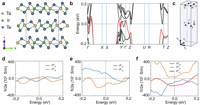
a Orthorhombic crystal unit cell of TaIrTe4. b Electronic structure of TaIrTe4 calculated via density functional theory along the high-symmetry lines in the Brillouin zone shown in c. d–f Calculated intrinsic spin Hall conductivity, representing configurations of spin current with spin polarization along a-, b-, and c-axis, respectively. The magnitude of the unconventional spin Hall conductivity σzzx at the Fermi level is determined mostly by the band marked as red in b.
To unveil the origin of the unconventional SHE, we have performed first-principles calculations of TaIrTe4 (see Methods for computational details). As shown in Fig. 6, our results reveal a large spin splitting of bands near the Fermi level due to SOC, and the presence of seven spin Hall conductivity components: six conventional (\({\sigma }_{{jk}}^{i}\) with i ≠ j ≠ k) and one unconventional component \({\sigma }_{{ZX}}^{Z}\), with the latter showing a magnitude comparable to the conventional components. The unconventional SHE at the Fermi level reaches σSH = 1.56 × 10⁴ ħ/2e (Ωm)–1, in agreement with experimental values reported for TaIrTe4 (1.47–5.44)x104 ħ/2e (Ωm)–1 8,9,18, which vary depending on experimental conditions and sample characteristics. Although previous studies attributed its presence to the topological properties of the surface8, our calculations show that a large unconventional SHE occurs even in the bulk.
We analyzed the crystal symmetry in more detail by directly applying symmetry operations, revealing that the relaxed structures exhibit a slight deviation from SG 31. This small structural distortion reduces the symmetry to either SG 6 (Pm) or SG 1 (P1), depending on the specified numerical precision (see Supplementary Note 9 for details). In both cases, the two-fold screw symmetry which normally prohibits unconventional SHE is absent, thus allowing for out-of-plane spin polarization of spin current. Structural distortion could further increase near the surface, potentially enhancing the generated spin accumulation. Therefore, from a symmetry perspective, the unconventional SHE component is justified, while its magnitude arises from the electronic properties, as discussed in Supplementary Materials.