The SFG-BSA configuration
Figure 1a shows a schematic of the SFG-BSA setup. A type-0 PPLN/W is incorporated in a Sagnac interferometer to extract two of the four Bell states in the polarization degree of freedom. It should be noted that this degree of freedom was preferred over the time degree of freedom, as the latter incurs photon losses by configuring the measurement system with a passive Franson interferometer17. In contrast to MZI-based configurations18, our SFG-BSA does not require phase stabilization between horizontally (H-) and vertically (V-) polarized photons. Thus, it can be viewed as a time-reversal of the polarization-entangled photon-pair generation using a Sagnac interferometer with a PPLN/W16,19,20. In this configuration (Fig. 1a), no SFG photon is produced if the two input photons are H- and V-polarized, respectively. However, if both input photons are V-(H-)polarized, they propagate clockwise (counterclockwise) through the interferometer to produce V-(H-)polarized SFG photons, respectively.
Fig. 1: SFG-BSA and SFG-based entanglement swapping.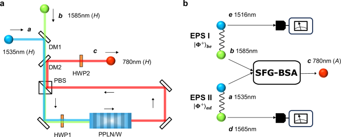
a Schematic of the SFG-BSA, showing the operation for two H-polarized input photons in modes a and b, which are combined into a single spatial mode by dichroic mirror 1 (DM1). They transmit through a polarization beamsplitter (PBS). Then, they flip to V polarization by half-waveplate 1 (HWP1). At the PPLN/W, the V-polarized photons in modes a and b are converted to a V-polarized single photon in mode c via the SFG process. Finally, the SFG photon is extracted by DM2, and its polarization is flipped back to H-polarization by HWP2. b Schematic of the SFG-based entanglement swapping. Detection of the D-/A-polarized SFG photon in mode c at 780 nm heralds the creation of entanglement between the photons in modes d and e.
This can be further discussed through the interaction Hamiltonian:
$$\hat{H}=i\hslash \chi \left({\hat{a}}_{H}{\hat{b}}_{H}{\hat{c}}_{H}^{{{\dagger}} }+{\hat{a}}_{V}{\hat{b}}_{V}{\hat{c}}_{V}^{{{\dagger}} }\right)+{{{\rm{H.c.}}}},$$
(1)
where \({\hat{a}}_{k}\) and \({\hat{b}}_{k}\) are annihilation operators of single photons with polarization k ∈ {H, V} in the input modes a and b, respectively, \({\hat{c}}_{k}\) is an annihilation operator of a k-polarized single photon in the output mode c, H.c. is the Hermitian conjugate, and ℏ is the Dirac constant. Here, \(\chi \in {\mathbb{R}}\) is a coupling constant that includes the nonlinear susceptibility of PPLN/W, and it is assumed to be independent of the polarization of the input photons. In addition, we assume that the sum of the photon numbers in the input modes a and b does not exceed two, and we consider only the lowest order of χ. These assumptions are made to describe the ideal operation of the SFG-BSA. The more realistic situations, including polarization dependency of χ and multiphoton inputs, are considered in the Theoretical analysis in the Methods section. In the case where one photon is generated in mode c as a success event, the corresponding Kraus operator is given by
$$\hat{K}=\sqrt{{\eta }_{{{{\rm{SFG}}}}}}({\left\vert H\right\rangle }_{c}{\left\langle HH\right\vert }_{ab}+{\left\vert V\right\rangle }_{c}{\left\langle VV\right\vert }_{ab}),$$
(2)
where ηSFG ≔ (χτ)2 and \({\left\vert k\right\rangle }_{a}:={\hat{a}}_{k}^{{{\dagger}} }\left\vert {{{\rm{vac}}}}\right\rangle\) for k ∈ {H, V} and so on. Here, τ is the travel time of the input photons through the nonlinear medium and \(\left\vert {{{\rm{vac}}}}\right\rangle\) is a vacuum state. By detecting a diagonally (D-) or anti-diagonally (A-) polarized SFG photon in mode c (defined by \({\left\vert D\right\rangle }_{c}:=({\left\vert H\right\rangle }_{c}+{\left\vert V\right\rangle }_{c})/\sqrt{2}\) and \({\left\vert A\right\rangle }_{c}:=({\left\vert H\right\rangle }_{c}-{\left\vert V\right\rangle }_{c})/\sqrt{2}\)), the projection on a Bell state \({\left\vert {\Phi }^{+}\right\rangle }_{ab}:=\frac{1}{\sqrt{2}}({\left\vert HH\right\rangle }_{ab}+{\left\vert VV\right\rangle }_{ab})\) or \({\left\vert {\Phi }^{-}\right\rangle }_{ab}:=\frac{1}{\sqrt{2}}({\left\vert HH\right\rangle }_{ab}-{\left\vert VV\right\rangle }_{ab})\) will be respectively performed, which corresponds to a quantum parity check.
Compared to a linear-optical BSA4,5,20,21,22,23, the SFG-BSA offers the following unique benefits. First, it aids faithful entanglement swapping based on probabilistic photon pair sources such as SPDC8, in which detection of an SFG photon deterministically heralds the creation of an entangled photon pair. This makes it well-suited for a long-distance loophole-free Bell test and device-independent quantum key distribution24. Interestingly, this principle allows tolerance against optical loss for entanglement swapping (details are given in the next section). Second, by adding another SFG-BSA for odd-parity inputs, it enables a complete Bell-state measurement that distinguishes all four Bell states without employing ancillary systems7. Finally, it allows entangling operations between different-color photons, which is useful for building multi-user entanglement networks13.
Figure 1b describes the entanglement swapping experiment based on the SFG-BSA. EPS I and EPS II generate two maximally entangled photon pairs \({\vert {\Phi }^{+}\rangle }_{ad}\otimes {\vert {\Phi }^{+}\rangle }_{be}\) and the SFG-BSA is performed on the photons in modes a and b, yielding \(_{c}\langle D(A)\vert \hat{K}{\vert {\Phi }^{+}\rangle }_{ad}\otimes {\vert {\Phi }^{+}\rangle }_{be}\propto {\vert {\Phi }^{+(-)}\rangle }_{de}\), respectively. The overall success probability is \({\sum }_{l\in \{D,A\}}{| }_{c}\langle l\vert \hat{K}{\vert {\Phi }^{+}\rangle }_{ad}\otimes {\vert {\Phi }^{+}\rangle }_{be}{| }^{2}={\eta }_{{{{\rm{SFG}}}}}/2\). The experimental success probability is ηSFG/4, considering that only one of the D- or A-polarized portions is measured.
Robustness of SFG-BSA against optical losses
To see the loss tolerance of the SFG-based entanglement swapping with probabilistic sources, we consider error events of the lowest order, where two photon pairs are generated by EPS I and one photon pair is generated by EPS II. In the presence of high channel loss, the dominant error event is the loss of a single photon among the three photons transmitted through the channel. This type of event can be categorized into two distinct types. First, one photon from EPS I is lost, and one photon from each of EPS I and EPS II successfully arrives at the BSA, which results in a coincidence detection. Second, one photon from EPS II is lost, and a coincidence detection is induced by two photons from EPS I. Although the first error event commonly occurs in the linear-optical BSA and SFG-BSA, the second error event can be excluded using the SFG-BSA. The reason is that the SFG occurs only when at least one photon arrives from each EPS, which results in an increase in the robustness of the SFG-BSA against optical loss. Let γ2 be the respective photon pair generation probability of EPS I and EPS II, and let t be the transmittance of each channel. Then, the probabilities of the first and second error events are given by 2γ6t2(1 − t) and γ6t2(1 − t), respectively. Thus, 1/3 of the error events are excluded using SFG-BSA. More detailed analysis is given in Supplementary Note 1 and 2.
SFG-BSA unit
The SFG-BSA unit consists of an in-house type-0 MgO-doped PPLN ridge waveguide (PPLN/W3) with free space coupling (length: 6.3 cm). Details of device fabrication are given in Supplementary Note 5. To estimate the single-photon SFG efficiency, we used coherent light pulses centered at 1535 and 1585 nm. These pulses were generated according to the difference-frequency generation (DFG) at EPS I and II in Fig. 2 with the pulsed pump at 775 nm and the two additional continuous wave lasers at 1565 and 1516 nm, respectively. Their coupling efficiencies to PPLN/W3 were measured to be 0.77 and 0.89, respectively, indicating a large mode matching between the input photon and waveguide modes. The estimated spatial profiles of photons in modes a, b and c are shown in Supplementary Note 6. By measuring the average power of the DFG pulses and the count rate of the SFG photons, the internal SFG conversion efficiency for single-photon inputs can be estimated as
$${\eta }_{{{{\rm{SFG}}}}}=\frac{{C}_{{{{\rm{SFG}}}}}}{{\eta }_{t}{\eta }_{d}\,f}\times \frac{hcf}{{P}_{a}{\lambda }_{a}}\times \frac{hcf}{{P}_{b}{\lambda }_{b}},$$
(3)
where c is the speed of light, h is Planck’s constant, ηt and ηd are the transmittance of the system and the quantum efficiency of the SNSPD used to detect the SFG photons, respectively. In addition, Pa(b) and λa(b) are the average power per mode and wavelength of the DFG pulses in modes a and b, respectively. CSFG is the count rate of the SFG photons, and f = 1.0 GHz is the repetition rate of the DFG pulses. Using the experimental parameters summarized in Table 1, we obtained \({\eta }_{{{{\rm{SFG}}}}}^{H}=2.31\times 1{0}^{-8}\) and \({\eta }_{{{{\rm{SFG}}}}}^{V}=2.35\times 1{0}^{-8}\) for H- and V-polarized inputs, respectively.
Fig. 2: Experimental setup for the SFG-based entanglement swapping.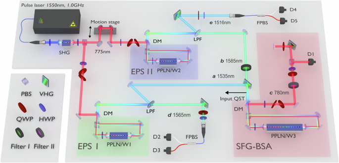
Pump pulses centered at 775 nm with a 1.0 GHz repetition rate is prepared by second harmonic generation (SHG) of the electro-optic comb centered at 1550 nm and used to pump EPS I and II. Each EPS consists of a PPLN/W in a Sagnac interferometer with a polarizing beamsplitter (PBS). The signal and idler photons at telecom wavelengths are divided into different spatial modes according to low-pass filters (LPFs). The photon in mode a at 1535 nm and the photon in mode b at 1585 nm are narrowed by a volume holographic grating (VHG) and band-pass filter (Filter I), respectively, and they are fed into the SFG-BSA unit. A flip mirror (not shown) just before the SFG-BSA is used to perform the quantum state tomography (QST) on the input quantum states. The output SFG photon in mode c at 780 nm is extracted by a dichroic mirror (DM) and passes through the band pass filter (Filter II) and is diffracted twice by a VHG. The polarization of the SFG photon is projected on the A-polarization by means of a quarter-waveplate (QWP), a half-waveplate (HWP), and PBS. The photon-detection signal from the SNSPD (D1) is used as the start signal of a time-to-digital converter (not shown). The photons in modes d and e are diffracted by VHGs. The polarization correlation of the swapped state \({\hat{\rho }}_{de}\) is evaluated by QWPs, HWPs, and fiber-based PBSs (FPBSs), followed by SNSPDs (D2-D5).
Table 1 Parameters of the SFG-BSA unitSFG-based quantum teleportation
To assess our SFG-BSA unit, we performed a quantum teleportation experiment. The input light to be teleported was generated by performing DFG at EPS II. We prepared H-, A-, and right circularly (R-) polarized weak coherent light as input states, and we set the average photon number at 0.95 per pulse. Then, we reconstructed the density matrices of the input states by conducting quantum state tomography25. Figure 3a shows an example of the density matrix for the A-polarized state (the density matrices of the H- and R-polarized input states are shown in Supplementary Note 3). The fidelities of the H-, A- and R-polarized states are \(\left\langle H\right\vert {\hat{\rho }}_{b}\left\vert H\right\rangle=0.97050(9)\), \(\left\langle A\right\vert {\hat{\rho }}_{b}\left\vert A\right\rangle=0.99735(3)\) and \(\left\langle R\right\vert {\hat{\rho }}_{b}\left\vert R\right\rangle=0.97500(8)\), respectively, and here \(\left\vert R\right\rangle :=(\left\vert H\right\rangle+i\left\vert V\right\rangle )/\sqrt{2}\). The fidelity errors correspond to the standard deviations with the assumption of Poisson statistics for the photon counts. In addition, we prepared an entangled photon pair using EPS I, whose density matrix is shown in Fig. 3b. The fidelity to the ideal state \(\left\vert {\Phi }^{+}\right\rangle\) is \(\left\langle {\Phi }^{+}\right\vert {\hat{\rho }}_{ad}\left\vert {\Phi }^{+}\right\rangle=0.9163(4)\). We input the weak coherent light in mode b and the photon in mode a into the SFG-BSA. Under the condition that a D-polarized SFG photon was detected by D1, we performed the quantum state tomography on the photon in mode d (see Fig. 2). Figure 3c and d show the density matrix of the teleported state and the raw detection counts for the A-polarized input, respectively. The fidelity is 0.890(30), and the measurement time is 13 h for each basis state. For H- and R-polarized inputs, the fidelities are 0.893(28) and 0.840(39), respectively. These values significantly exceed the classical limit of 2/326, indicating the high fidelity of the SFG-BSA for inputs at the single photon level. It is worth noting that the results in ref. 7 were reported as quantum teleportation using SFG with 1010 input photons on average. Nevertheless, these results can be rather understood as a quantum frequency conversion27,28,29 in the weak pump regime, in contrast to the present quantum-teleportation experiment with single-photon-level inputs. This is because in the situation of ref. 7, the input light is regarded as the pump light for the quantum frequency conversion. Hence, the quantum-teleportation-like behavior is observed under the condition that the conversion efficiency of the quantum frequency conversion can be approximately regarded as proportional to the average intensity of the input light. In the strong-pump regime, where the above approximation does not hold, the polarization state is no longer transferred. A detailed discussion is given in Supplementary Note 4.
Fig. 3: Experimental results for the SFG-based quantum teleportation.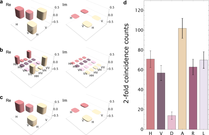
a Density matrix of the A-polarized input state. The left (right) of each plot shows the real (imaginary) part of the density matrix, respectively. b Density matrix of the entangled state. c Density matrix of the teleported state. d Raw counts of the teleported photons for the A-polarized input light. The measurement time was 13 h for each basis state. Here, R and L represent right and left circular polarizations, respectively. The error bars were calculated assuming the Poisson statistics.
SFG-based entanglement swapping
Figure 2 depicts the experimental setup for entanglement swapping. We prepared two initial entangled photon pairs \({\hat{\rho }}_{ad}\) and \({\hat{\rho }}_{be}\) as input states. Their density matrices are shown in Figs. 4a and b, respectively. The fidelities are \(\left\langle {\Phi }^{+}\right\vert {\hat{\rho }}_{ad}\left\vert {\Phi }^{+}\right\rangle=0.9079(4)\) and \(\left\langle {\Phi }^{+}\right\vert {\hat{\rho }}_{be}\left\vert {\Phi }^{+}\right\rangle=0.8775(6)\). The photons in modes a and b were combined by a volume holographic grating and fed to the SFG-BSA. When an A-polarized SFG photon at 780 nm is detected by the SNSPD (D1), both output ports of the fiber-based polarizing beamsplitter were simultaneously measured using SNSPDs D2, D3, D4, and D5. The low-noise detection of the SFG photon in mode c was enabled by D1, which possesses a high quantum efficiency (ηd = 85%) and an ultralow dark count rate (Rd= 0.15 Hz). The typical quantum efficiency of D2, D3, D4, and D5 was 75%. Figure 4c shows an example of the two-fold coincidence between D1 and D2. We observe a signal peak corresponding to the coincidence detection between photons in modes c and d. Background counts are primarily caused by the coincidence between the dark count at D1 and the detection of the photon in mode d at D2. We used a coincidence window of τw = 448 ps, corresponding to seven bins around the signal peak, shown by the red bars in Fig. 4c. The three-fold coincidence histogram among D1, D2, and D4 with bin widths τw is shown in Fig. 4d. We clearly identify a signal peak corresponding to \(\left\langle VV\right\vert {\hat{\rho }}_{de}\left\vert VV\right\rangle\), with a measured SNR equal to 5.57 ± 1.48. We performed Z-basis measurements that distinguish the H/V polarization and X-basis measurements that distinguish the D/A polarization on the photons in modes d and e. Each measurement (30 min duration) was repeated 452 times, resulting in an overall measurement time of 226 h for each basis state. The coincidence counts of the swapped state for eight basis states are shown in Figs. 4e and f. The polarization correlation corresponding to the target swapped state \({\left\vert {\Phi }^{-}\right\rangle }_{de}:=({\left\vert HH\right\rangle }_{de}-{\left\vert VV\right\rangle }_{de})/\sqrt{2}=({\left\vert DA\right\rangle }_{de}+{\left\vert AD\right\rangle }_{de})/\sqrt{2}\) is clearly identified. We evaluated the quality of the swapped state by the visibilities for Z-basis (\({V}_{{{{\rm{Z}}}}}:=\left\langle {\hat{Z}}_{d}{\hat{Z}}_{e}\right\rangle\)) and X-basis (\({V}_{{{{\rm{X}}}}}:=-\left\langle {\hat{X}}_{d}{\hat{X}}_{e}\right\rangle\)), where \(\hat{Z}:=\left\vert H\right\rangle \left\langle H\right\vert -\left\vert V\right\rangle \left\langle V\right\vert\) and \(\hat{X}:=\left\vert H\right\rangle \left\langle V\right\vert+\left\vert V\right\rangle \left\langle H\right\vert\) are Pauli operators. We observed high visibilities of VZ = 0.833(92) and VX = 0.706(121). Although these parameters are not sufficient to reconstruct the complete density matrix, they help to estimate the lower bound of the fidelity F ≥ Flow = (VZ + VX)/230,31. The experimental value of Flow was found to be equal to 0.770(76), which confirms that the swapped state is strongly entangled.
Fig. 4: Experimental results for the SFG-based entanglement swapping.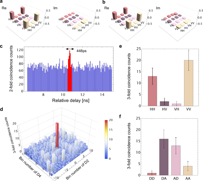
a, b Density matrices of the input states from EPS I and II, respectively. c Two-fold coincidence counts between D1 and D2. We employed a 448-ps coincidence window corresponding to seven bins around the signal peak. d Three-fold coincidence counts among D1, D2, and D4. The center bin corresponds to the signal event. The waveplates were set so that D2 and D4 detect V-polarized portions of photons d and e, respectively. The measurement time was 226 h. e, f Raw detection counts of the swapped state for each basis state. The error bars were calculated assuming the Poisson statistics.