Linear passive circulator
Our paradigm revisits the concept established by the acoustic Zeeman circulator20, renowned for its remarkable nonreciprocity. As illustrated in Fig. 1a, the acoustic circulator utilizes a circulating fluid that facilitates a frequency shift of \(\Delta \omega\), leading to the resonant frequency splitting between right- and left-handed modes. Mirroring the electronic Zeeman effect, an incoming sound at port I is unevenly split into two distinct frequency branches, \({\omega }_{0}\to {\omega }_{+}\ {{\rm{and}}}\ {\omega }_{0}\to {\omega }_{-}\), respectively. The operational parameters, such as the speed of the circulating air, are calibrated based on the total quality factor (Q-factor) of the dipolar resonance, transforming the system into a highly efficient acoustic nonreciprocal circulator. Notably, the specific velocity of the circulating fluid emerges as a crucial factor for breaking the system reciprocity, while total transmission and blocking at port II and III are subject to precise conditions of rigorous frequency \({\omega }_{0}\) and cavity radius, pointing to the stringent nature of this design. The limitations inherent in the above scheme have propelled us to explore new strategies for realizing an effective acoustic or elastic circulator without external disturbances, active modulation, or nonlinearity.
Fig. 1: Illustration of elastic-wave circulator based on wave-vector modulation.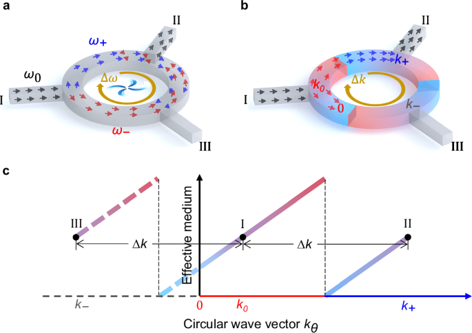
a Nonreciprocal acoustic circulator by implementing biased angular momentum. The inputting angular frequency \({\omega }_{0}\) is split into \({\omega }_{+}\) and \({\omega }_{-}\) by circulating field, \({\omega }_{\pm }={\omega }_{0}\pm \Delta \omega\). b Elastic-wave circulator by tailoring wave vector. The inputting circular wave vector \({k}_{0}\) is modulated into \({k}_{+}\) and \({k}_{-}\), \({k}_{\pm }={k}_{0}\pm \Delta k\). Here, \({k}_{+} > 0,{k}_{-} c Schematic of elastic-wave circulator based on wave vector modulation. The gradient color of the line indicates the variation of circular wave vector \({k}_{\theta }\) with different arrangements of effective medium. The mode transition is represented by the red and blue axis. Port I, port II and port III have the same effective medium.
In this pursuit, we first devised a novel method to achieve one-way elastic circulator purely through linear and passive media, focusing on the splitting of wave vector rather than angular frequency. Illustrated in Fig. 1b, our design features three identical curved waveguides with chiral symmetric arrangement at \({120}^{\circ }\) intervals. Specifically examining incident waves from port I, the circular wave vector component, \({k}_{\theta }\), is engineered to increase gradually along the clockwise direction. Consequently, at port II, \({k}_{\theta }\) will transition to \({k}_{+}\) \(({k}_{+}={k}_{0}+\Delta k > 0)\), thereby facilitating smooth propagation of incoming waves into port II. Conversely, to hinder wave propagation along the counter-clockwise direction, the circular wave vector component \({k}_{\theta }\) at port I should be diminished to zero before reaching port III. Owing to the symmetry of the three interlinked waveguides, the linear and passive system will only support one-way energy flowing, specifically in a clockwise sequence from port I to II, II to III, and III back to I.
To illustrate the tailoring physics, we present the variation of circular wave vector component, \({k}_{\theta }\), with varying waveguide mediums, as shown in Fig. 1c. Specifically, \({k}_{\theta }\) is expected to incrementally ascend from \({k}_{0}\) to \({k}_{+}\) between port I and II, depicted by the formular \({k}_{+}={k}_{0}+\Delta k\). To achieve this envisioned scenario, a smooth alteration in the medium’s effective properties is necessary. Nonetheless, the circulators at ports I, II, and III possess identical physical properties, achieving asymmetric transmission necessitates an intentional disruption of the waveguide’s spatial symmetry. This deliberate disruption inevitably introduces an interface characterized by a sudden shift in the effective properties. The abrupt interface not only requires break the spatial symmetry, but also ensures the continuity of wave vector. Concurrently, the resonant modes within the waveguide will be compelled to a transition from one mode (represented on the \(x\)-axis in red) to another (represented on the \(x\)-axis in blue) at this strategically placed interface. Therefore, the critical challenge for smooth propagation from port I to port II lies in the seamless realization of a perfect mode transition at the abrupt interface.
On the contrary, to block wave propagation along the anticlockwise direction, the wave vector \({k}_{\theta }\) at port I should decrease and reach zero prior to port III. The zero wave vector implies that the waves will be trapped here and incapable of propagating forward. Mathematically, \({k}_{\theta }\) at port III has a negative value \({k}_{-}\), where \({{k}_{-}=k}_{0}-\Delta k\). However, we want to emphasize that the negative wave vector \({k}_{-}\) (\(x\) axis in dashed line) is not actually obtained in practice because of the terminate of wave propagation at zero wave vector location. Therefore, the second key point for wave trapping before port III is tailoring the wave vector \({k}_{\theta }\) from \({k}_{0}\) to zero in continuous waveguide medium. By doing so, without breaking the reciprocity of system, we obtain nonsymmetrical scattering matrix,
$$S=\left[\begin{array}{ccc}0 & 1 & 0\\ 0 & 0 & 1\\ 1 & 0 & 0\end{array}\right]$$
(1)
Realization of elastic-wave circulator via wave-vector modulation
Achieving perfect mode transition and suppression, simultaneously, along the opposite directions in an identical waveguide is the key factor to design the linear passive elastic circulator. Figure 2a shows the circulator with varying unit cells along the waveguide edges. The unit cell is marked \({\mbox{A}}\) at the three ports \({{\rm{I}}}\), \({{\rm{II}}}\), \({{\rm{III}}}\). The abrupt interface featuring substantial dissimilarity of unit cells (\({{\mbox{B}}}_{1}\) and \({{\mbox{B}}}_{2}\)) at two sides exists which is denoted by yellow dashed line. Another unit cell is marked C where mode suppression occurs and elastic waves are reflected back. The frequency spectrum of flexural modes for a unit cell is calculated and shown in Fig. 2b. The length, thickness, width of unit cell are \(H=10\, {{\mbox{mm}}}\), \(\tau=1.5\, {\mbox{mm}}\), \(\delta=20\,{\mbox{mm}}\), respectively. Two same cantilever beams are connected on both sides, with a width of \(h=5\,{\mbox{mm}}\). For a specific cantilever beam with the length \(l\), the frequency spectrum profiles of unit cells can be calculated theoretically. A waveguide composed of the periodic arrangement of unit cells supports guided modes in the following form,
$${w}_{1}=\left\{\begin{array}{cc}\left[P\cos h\left({\xi }_{1}y\right)+Q\cos h\left({\xi }_{2}\, y\right)\right]{e}^{-i{k}_{x}x} & ({\mbox{mode}}\ 1)\hfill \\ \left[P\cos \left({\xi }_{1}y\right)+Q\cos h\left({\xi }_{2}\, y\right)\right]{e}^{-i{k}_{x}x}\hfill & ({\mbox{mode}}\ 2)\end{array}\right.$$
(2)
wherein for mode 1, \({\xi }_{1}=\sqrt{{{k}_{x}}^{2}-{k}^{2}}\) and \({\xi }_{2}=\sqrt{{k}^{2}+{{k}_{x}}^{2}}\). For mode 2, \({\xi }_{1}=\sqrt{{k}^{2}-{{k}_{x}}^{2}}\) and \({\xi }_{2}=\sqrt{{k}^{2}+{{k}_{x}}^{2}}\). Since the width of cantilever beam is much smaller than the operating wavelength, we can only consider the fundamental mode in the cantilever beam,
$${w}_{2}=a\,{e}^{-{jky}}+b{e}^{\,{jky}}+c{e}^{-{ky}}+{{de}}^{{ky}}$$
(3)
Fig. 2: The mechanism of elastic-wave circulator.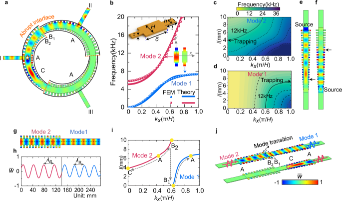
a The circulator model and one-way wave behavior. Several locations (\({\mbox{A}},{{\mbox{B}}}_{1},{{\mbox{B}}}_{2},{\mbox{C}}\)) are selected to analyze the evolution of wave vector. b The frequency spectrum of flexural waves. The unit cell configuration and the eigenmodes of mode 1 and mode 2 are provided as the insets. \(H=10\, {{\mbox{mm}}},{h}=5\, {\mbox{mm}},\delta=20\, {\mbox{mm}},\tau=1.5\,{\mbox{mm}}.\) \(l\) is the cantilever beam length in the unit cell. c, d The frequency spectrum contour of mode 2 and mode 1 with different unit cells. e, f Wave trapping of mode 2 and mode 1 at 12 kHz. The trapping locations are marked by black arrows, which correspond to that in (c, d). g Nearly perfect mode transition at the abrupt interface. h Normalized out-of-plane displacement \(\bar{w}\) along the middle line of waveguide in (g). \({\lambda }_{B}\) represents the wave length of mode 2 and mode 1. i The evolution of wave vector \({k}_{x}\) with different unit cells at 12 kHz. j Simulated displacement fields \(\bar{w}\) in one-way waveguide, which has same unit cells at two ports. The abrupt interface in the middle allows mode transition and suppression for the left and right incident, respectively.
Considering the free boundary condition at the end of cantilever beam and applying the continuity conditions of displacement, slope, bending moment, shear force at the interface between cantilever beam and waveguide channel, we can derive the following relation (see Supplementary Note1 and Supplementary Fig. S1 for details).
$${{\boldsymbol{T}}}\cdot {\left[P\, Q\, a\, b\, c\, d\right]}^{T}={{\bf{0}}}$$
(4)
Given the cantilever beam \(l=10\,{\mbox{mm}}\) as an example, the analytical dispersion bands (Theory) are derived by solving \(\det \left({{\boldsymbol{T}}}\right)=0\), and agree well with numerical solutions (FEM), as compared in Fig. 2b. The eigenstates of two modes are provided, in which mode 1 \(({k}_{x} > k)\) and mode 2 \(({k}_{x} exhibit the hallmark traits of surface waves and propagating waves, respectively. We numerically calculated the dispersion bands when the length of cantilever beam ranges from \(0\,{\mbox{mm}}\) to \(10\,{\mbox{mm}}\). The dispersion spectrum contours for mode 2 and mode 1 are depicted in Fig. 2c, d, respectively. The equifrequency line gives the relations between wave vector \({k}_{x}\) and cantilever beam length \(l\). We take the equifrequency line at 12 kHz (black solid line) for the following discussion. The wavevector \({k}_{x}\) can be smoothly tailored by increasing or decreasing \(l\) until reaching the Brillouin zone boundary \(0\) or \(\pi /H\). Specifically, if the waveguide is built with varying cantilever beam length \(l\), the wave vector \({k}_{x}\) of mode 2 can be decreased to \(0\) at the location \(l=4.1{\mbox{mm}}\), which implies wave trapping of mode 2. The corresponding numerical result is shown in Fig. 2e. The similar phenomenon can also be found for mode 1. With the increase of cantilever beam length \(l\), the wave vector \({k}_{x}\) will reach \(\pi /H\) at the location \(l=7.1\,{\mbox{mm}}\). The simulated wave trapping of mode 1 can be observed in Fig. 2f. One of key factors for the unidirectional circulator, wave trapping, can be achieved based on the above strategy.
Besides wave trapping, another key factor is to realize perfect mode transition between surface mode (mode 1) and propagation mode (mode 2). For this pursuit, we utilize wave vector \({k}_{x}\) of two modes to establish the matching impedance. We deduced that the impedance \(Z\) of waveguide along the wave propagating direction as
$$Z={iD}\left[\frac{{k}^{2}\nu }{{k}_{x}}+{k}_{x}(1-\nu )\right]$$
(5)
where \(D,{k},\nu\) are bending stiffness, wave number, Poisson’s ratio of host plate, respectively. \({k}_{x}\) is the wave vector along the wave propagating direction \(x\) (see Supplementary Note 2, Supplementary Fig. S2 and Fig. S3 for detailed derivation). The impedance \(Z\) only depends on the wave vector \({k}_{x}\) if the waveguide channel keeps constant, which means perfect mode transition can be generated if the two modes possess the identical wave vector \({k}_{x}\). From the dispersion spectrum contours, we notice that mode 2 and mode 1 have the same wave vector \({k}_{x}\) when \(l=10\,{\mbox{mm}}\) and \(l=0\,{\mbox{mm}}\) at 12 kHz, which illustrates that impedance matching condition can be satisfied at the abrupt interface between two entirely dissimilar unit cells. To demonstrate this point, we deployed the full wave simulation to display wave propagation around the abrupt interface. Figure 2g exhibits that mode 2 and mode 1 can be transferred smoothly at the abrupt interface with a slight backscattering. The transmission coefficients between different unit cells are calculated and provided in Supplementary Note 3 and Fig. S4. The normalized out-of-plane displacement \(\bar{w}\) along the middle line of the waveguide (black dashed line) is shown in Fig. 2h. We can clearly observe that the amplitude and wavelength almost remain unchanged at both sides of the abrupt interface.
The nearly perfect mode transition facilitates smooth wave propagation at the abrupt interface. In light of this principle, we propose a framework for one-way waveguide with identical end ports. It incorporates two gradient waveguides connected by an abrupt interface, as detailed in Fig. 2j. Both the left and right ports have the same unit cell \({\mbox{A}}\) and the bilateral unit cells of abrupt interface are marked by \({{\mbox{B}}}_{2}\) and \({{\mbox{B}}}_{1}\). When the flexural waves inputs from the left to the right, they will experience the path \({\mbox{A}}\to {{\mbox{B}}}_{2}\to {{\mbox{B}}}_{1}\to {\mbox{C}}\to {\mbox{A}}\). Figure 2i exhibits the evolution of wave vector \({k}_{x}\) with the changing of unit cells. The flexural waves mostly coupled into mode 2 at the location \({\mbox{A}}\) will arrive at the left side of interface, where mode 2 at \({{\mbox{B}}}_{2}\) is converted into mode 1 at \({{\mbox{B}}}_{1}\). Here, we place the source on the middle line of the ring near port I, which is essential to ensure that mode 2 is dominantly coupled. If the source is placed in the port, the flexural waves will not couple into mode 2, and a pure asymmetric transmission cannot be guaranteed. The reasons behind it are fully discussed in Supplementary Note 4, Fig. S5, and Fig. S6. After that, flexural waves of mode 1 will be delivered into the right port. During the whole process, wave vector \({k}_{x}\) keeps increasing evenly which ensures the highly efficient transmission from the left to right. Conversely, when the flexural waves input from the right to the left, they will be trapped at location \({\mbox{C}}\). The intrinsic mechanism can also be exploited by analyzing the changes of wave vector \({k}_{x}\) in Fig. 2i. During the path \({\mbox{A}}\to {\mbox{C}}\), the wave vector \({k}_{x}\) of mode 2 will undergo sustainable decrease until reaching zero at location \({\mbox{C}}\). Mode transition is unlikely to happen here because no same wave vector can be found at the mode 1 branch. As a result, flexural waves in mode 2 will be reflected at location \({\mbox{C}}\). The above statements are validated by numerical simulation in Fig. 2j, demonstrating that the proposed waveguide with same ports allows flexural waves propagating from the left smoothly but almost totally blocked from the right.
Based on this prototype, we constructed an engineered circulator with three interconnected waveguides (Fig. 2a). Here we place the excitation source at port I (marked by a white star) and the full-wave simulation of normalized out-of-plane displacement is exhibited at 12 kHz. Along the clockwise direction, the flexural waves coupled into mode 2 at port \({{\rm{I}}}\), enable seamless propagation into the abrupt interface. After passing through the interface, mode 2 is converted into mode 1 and continue propagating into the port \({{\rm{II}}}\). Conversely, waves along the anticlockwise direction can be only trapped into location \({\mbox{C}}\) prior to the interface and bounced back, preventing energy flux from reaching port III. To the end, the robust effectiveness of this linear passive circulator with three-fold rotation symmetry is demonstrated in filtering and directing wave propagation as designed. The transient responses in time domain are provided in Supplementary Movie 1.
Experimental realization
To verify the one-way propagation in the designed elastic-wave circulator, we built the experimental setup as illustrated in Fig. 3a. The circulator is fabricated through wire electrical-discharge machining on a steel plate with a thickness of \(1.5\, {\mbox{mm}}\). The diameter of circulator is \(200\, {\mbox{mm}}\) and the waveguide channel has a width of \(20\, {\mbox{mm}}\). The inset shows an enlarged view of the abrupt interface. We conducted a series of experimental verifications by placing the point source near port I, port II and port III, respectively. The experimental results at 11.2 kHz are exhibited in Fig. 3b. When the source is placed near port I, the flexural waves energy can only flow clockwise from port I into port II but not port III. Similar one-way propagation phenomena are also captured for other source locations. Because of the rotational symmetry of circulator, the displacement fields should remain identical regardless of which port the source is placed at. However, some discrepancies can be observed especially within the input and output channels, which may be induced by manufacturing and measurement errors. To clarify this, the corresponding numerical simulations and discussions are provided in the Supplementary Note 5 and Fig. S7.
Fig. 3: The experimental demonstration of elastic-wave circulator.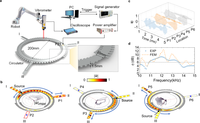
a The setup of experimental platform. b The experimentally measured normalized out-of-plane amplitude \(|\bar{w}|\) at 11.2 kHz when the source is placed near port I, port II and port III, respectively. The black solid lines in the circulators represent the maximum of \(|\bar{w}|\) at different azimuths, and the red box regions are selected for the calculation of contrast ratio \(\eta\). c The measured normalized out-of-plane displacement \(\bar{w}\) in time domain. P1 ~ P6 are selected in the centers of six ports in (b). The blue, orange and gray lines correspond to the inputting near port I, port II and port III, respectively. d Numerically simulated (FEM) and experimentally measured (EXP) contrast ratio \(\eta\) as the function of frequency. The baseline of extremely high asymmetry is \(\eta=6\), above which highly asymmetry can be obtained from 11 to 13.5 kHz.
In each panel of Fig. 3b, the normalized maximum amplitudes \({|\bar{w}|}_{\max }\) varying with the azimuth in the waveguide channel are shown inside the circulator. With the sustainable increase of wave vector \({k}_{x}\), energy gradually accumulates at waveguide edge along the clockwise direction. Conversely, the decrease of wave vector \({k}_{x}\) along the counterclockwise direction results in the stopping of flexural waves, where the peak value of \({|\bar{w}|}_{\max }\) appears and no energy flowing beyond this point. In each panel of Fig. 3b, we select two points (marked by blue stars) at the centers of outputting ports to analyze the displacement variations in time domain. As shown in Fig. 3c, the measured oscillating normalized out-of-plane displacement \(\bar{w}\) at clockwise outputting is significantly larger than that at anticlockwise outputting wherever the inputting is.
A contrast ratio is defined to quantitatively evaluate the circulator’s efficiency, which is denoted by \(\eta=10\log \frac{{\iint }_{{{\rm{II}}}}{|w|dS}}{{\iint }_{{{\rm{III}}}}{|w|}{dS}}=10\log \frac{\mathop{\sum }_{i=1}^{N}{{|w}}_{{{\rm{II}}}}|}{\mathop{\sum }_{i=1}^{N}{{|w}}_{{{\rm{III}}}}|}\). Here, two same-size regions (indicated by red boxes in Fig. 3b) are selected for the integration and \(N\) is the number of sampling points. The contrast ratio \(\eta\) ensures a reliable index to quantify the asymmetry when we sum up all the sampling points in the two regions. The numerical and experimental results are shown in Fig. 3d, in which \(\eta > 2\) can be observed from 10 kHz to 15 kHz, with an extremely high contrast ratio \(\eta > 6\) maintained within the range of 11 kHz to 13.5 kHz. The numerically simulated peak value (\(\eta=12.8\)) is larger than the experimentally measured value (\(\eta=9.0\)), which could be induced by manufacturing errors and material dissipation. The scattering characteristics of circulator from different inputting are provided in Supplementary Note 6 and Fig. S8. Although flexural waves can be mostly coupled to mode 2 when the source is placed in the ring, a few waves in other modes can also be generated, which will undermine the asymmetry effect to some extent. On the other side, the dominant flexural waves in mode 2 will experience the mode transition at the abrupt interface. In fact, the transmission rate cannot reach 100% perfectly, and not all the waves can be directed into port II. All these factors fundamentally limit the highest asymmetry efficiency \(\eta\) for the circulator. In short, the proposed passive elastic circulator demonstrates excellent asymmetry performance across a broad bandwidth. The experimental results confirm that the linear passive circulator, achieved by tailoring wave vectors \({k}_{x}\), allows flexural waves propagating only along the clockwise direction without relying on any external biased field or nonlinear media. Additional experimentally measured and numerically simulated normalized displacement fields \(\bar{w}\) at other frequencies and the transient responses are compared in the Supplementary Fig. S9 and Supplementary Movie 2.
Unidirectional demultiplexing routing
Perfect mode transition and wave trapping are crucial for one-way transmission of flexural waves through the proposed wave-vector-based circulator. By addressing these pivotal issues, a gradient waveguide with discrete unit cells can be engineered into a varying-section beam, acting as a simplified version of the circulator. Intriguingly, the meticulously designed elastic circulator can further overcome the constraint of source location limited in the channel, allowing flexural waves from any port to route along the clockwise direction. As depicted in Fig. 4a, we position excitation sources at both ends of the waveguide, where no cantilever beams are attached laterally. The waveguide channel width is 30 \({\mbox{mm}}\). On the left side of the abrupt interface, the cantilever beam length increases from \(l=0\,{\mbox{mm}}\) to \(l=10\,{\mbox{mm}}\) gradually. For the right side, the beam width increases linearly from \(\delta=22\,{\mbox{mm}}\) to \(\delta=30\,{\mbox{mm}}\). The full-wave simulation of normalized displacement field \(\bar{w}\) at 12.4 kHz is shown in the upper panel of Fig. 4a. The same asymmetric rectifying functionality as Fig. 2j is achieved by a more compact topology design.
Fig. 4: The improved design of elastic-wave circulator.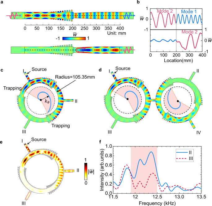
a The simulated out-of-plane displacement field \(\bar{w}\) for the simplified waveguide at 12.4 kHz. b The distribution of normalized out-of-plane displacement \(\bar{w}\) along the black dashed line in (a). c The simulated result of improved elastic-wave circulator when the source is placed in port I. The blue curved line inside the shaded region represents the circular wave vector \({k}_{\theta }\) from \(0\) to the maximum. The inner radius of circulator is \(105.35\,{\mbox{mm}}\). d A double elastic-wave circulators for unidirectional demultiplexing routing. e The experimentally measured normalized amplitude fields \(|\bar{w}|\) at 12.4 kHz. f The amplitude intensity of port II and port III as the function of frequency. The intensity is obtained by integrating the amplitude in the two red boxes of e. The shaded region represents significant asymmetry between two ports.
The corresponding normalized out-of-plane displacement \(\bar{w}\) along the central line of waveguide (black dashed line in Fig. 4a) is presented in Fig. 4b. For the incident waves from the left, the displacement amplitudes remain almost constant at both sides of interface, with a progressively increasing wave vector indicated by the decreasing wavelength. Conversely, incident waves from the right side are trapped before reaching the abrupt interface. The left-side flexural waves’ amplitude nearly vanishes compared to the right side, illustrating the absence of mode transition in this scenario.
We further utilize the simplified waveguides to build the single and demultiplexing elastic circulators, as illustrated in Fig. 4c, d, respectively. The simulated normalized out-of-plane displacement \(\bar{w}\) in the three-port circulator at 12.4 kHz is shown in Fig. 4c. Regardless of the excitation source’s placement, only clockwise propagating of flexural waves is allowed, demonstrating the complete realization of a mechanical circulator for asymmetrically routing flexural waves without relying on nonlinear material or unbiased field perturbations. The good performance of the improved circulator is also demonstrated by experimental measurement. We provide the experimentally measured displacement amplitude fields \(|\bar{w}|\) at 12.4 kHz in Fig. 4e, which show good agreement with the simulated results (Fig. 4c). The asymmetry intensity from 11.5 kHz to 13.5 kHz is evaluated by integrating the amplitude over port II and port III (Fig. 4f). Within the range of 11.9 kHz to 12.5 kHz, most of the energy from the source can arrive at port II with high asymmetry, demonstrating that a perfect elastic circulator can be achieved based on the modified design strategy.
Furthermore, we would like to elucidate the fact that flexural waves from port I will merely reach port II but not proceed to port III, which can be explained by wave trapping of mode 1. As the wave vector \({k}_{\theta }\) increases from port I to port II, flexural waves are converted into surface waves. If they continue propagating along the clockwise direction, \({k}_{\theta }\) reaches its maximum value \(\pi /H\) before the abrupt interface, causing the surface waves to be trapped and reflected (Fig. 4c). The blue Archimedes spiral inside the circulator exhibits the variation of wave vector, in which the shaded region indicates the energy transportation of flexural waves. Mode 2 and mode 1 are trapped at opposite ends of the spiral.
We extended the single circulator concept to design a double circulator prototype for unidirectional demultiplexing routing. As illustrated in Fig. 4d, one circulator connects bidirectionally to a mirror-symmetric counterpart. Consequently, energy flux from the source cannot enter ports II and III due to their equivalent placement. Between ports I and IV, the symmetric waveguide profile, with wave vector increasing firstly and then decreasing to its initial value (shaded region in Fig. 4d), ensures smooth, asymmetric flexural wave propagation from port I to port IV.