Design of a flat-band multi-BIC cavity
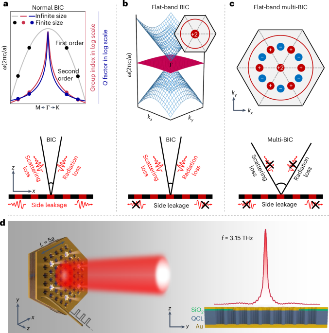
Our laser cavity design is constructed by etching periodic air holes through the active medium of a three-well resonant-phonon GaAs/Al0.15Ga0.85As designed terahertz QCL wafer to form a triangular photonic-lattice structure (Fig. 1d and Supplementary Figs. 1 and 2). The air holes feature a daisy-like shape, which facilitates the manipulation of the photonic band structure30,31. The shape can be written as r(ϕ) = r0 – rdcos(6ϕ). By forcing an accidental degeneracy between the isolated B mode and the doubly degenerated E1 and E2 modes (Supplementary Fig. 3), a distinct flat band intersecting with two linear dispersion bands (Dirac cone) at their apex can be achieved (Fig. 1b). The slow light effect, arising from the dispersionless nature of the flat band, provides excellent in-plane field confinement and considerably reduces side-leakage losses, even as the mode shifts away from the Γ point in finite-sized cavities. All three selected bands belong to different irreducible representations at the Γ point (B, E1 and E2) and decoupled from free space30, that is, typical symmetry-protected BIC modes32, which effectively mitigate radiation losses that may occur due to mode coupling when they come into proximity to each other33 (Supplementary Figs. 4 and 5). These non-radiative modes (with a theoretically infinite Q factor) are characterized by a polarization singularity (for example, the flat band) at the centre of the Brillouin zone. By tuning the lattice parameters, we further engineer a series of accidental BICs around the Γ point, giving rise to a unique feature denoted as ‘multi-BIC’ (Fig. 1c). The multi-BIC with a broad, high-Q region enable the cavity mode to stand robust against photonic finite-size effects, systematic disorders and structural imperfection, significantly suppressing radiation and scattering losses34,35,36,37,38.
Flat-band-enhanced in-plane mode confinement
We emphasize the advantages of the flat-band BIC mode (E1 mode; Fig. 2a (top)) by comparing it with the conventional BIC, that is, the B′ mode with C6v symmetry at the bottom of Fig. 2a (referred to as the ‘normal C6v-BIC’ hereafter). The full band structures and electric-field distributions within a unit cell for these photonic lattices are shown in Supplementary Fig. 6. As illustrated, the E1-irreducible photonic mode displays a remarkable flat-band feature in the entire region above the light cone, whereas the B′ mode features a quadratic band dispersion. To investigate their disparities on mode localization within a miniaturized photonic cavity (L = 5a), we calculated the fundamental modes of these two bands with distinct dispersion behaviours (Fig. 2b). Our simulations (Methods) are modelled strictly according to the actual device structure with a finite size, incorporating a typical absorption boundary (the outer unpatterned region), which also serves as wire bonding for pumping current injection39. The electric field (|Ez|) associated with the E1 mode is tightly confined to the centre of the cavity, in stark contrast to the B′ mode, which substantially leaks out of the patterned region, forming a near-plane wavefront away from the interfaces. The effective in-plane field confinement in the flat-band cavity arises from the ultralow group velocity with enhanced mode feedback. Figure 2c illustrates the group indices for bands featuring different dispersion characteristics. In particular, the group index of the E1 band exceeds that of the B′ band by approximately ten times as they deviate from the Γ point. Both cases exhibit negligible mode extension above the photonic-crystal slab, attributed to the non-radiative nature of the BICs. Further simulations based on a normal BIC in commonly used C4v-symmetric lattice structure are also performed (Supplementary Fig. 7). The consistent results collectively support the conclusion that a flat band with minimal dispersion indeed ensures effective in-plane confinement in miniaturized cavities.
Fig. 2: Comparison between the flat-band BIC mode and other normal BIC modes.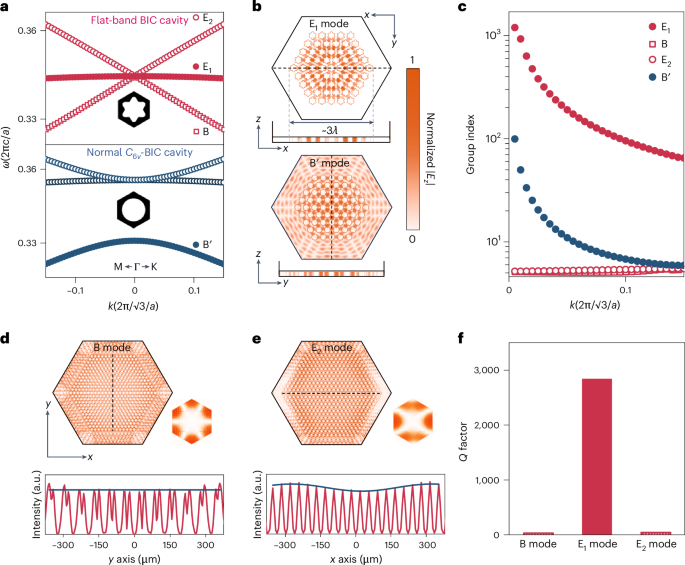
a, Calculated band diagrams of the daisy-like air-hole photonic crystal with flat-band BIC (top) and conventional circular air-hole structure with normal C6v-BIC. b, Near-field profiles in finite-sized cavities (L = 5a) corresponding to the fundamental mode of the E1 band (top; flat-band) and B′ band (bottom) in the corresponding data in a. c, Group indices for the representative modes computed from the corresponding Bloch-band structures. d,e, Near-field profiles of the fundamental modes belong to the two adjacent bands (B (d) and E2 (e) bands) with linear dispersion, for the cavity with L = 13a (top). Bottom, extracted electric-field intensity along the dashed line within the cavities. f, Calculated Q factors of the B, E1 and E2 modes with distinct band dispersion features, treating the pumped region as a lossless dielectric with absorbing boundaries (Methods). Here a flat-band BIC cavity with lattice parameters of a = 37.2 μm and r0 = 14.5 μm is adopted to exclude the influence of the multi-BIC, which will be discussed later in Fig. 3.
We also observed that the B and E2 bands, characterized by linear dispersion, exhibit an exceedingly low group index of ~5.2 near the Γ point, which suggests weak in-plane feedback and a limited localization effect. Direct examination of the effective index (Supplementary Fig. 8) based on the band structure reveals a characteristic ‘zero-index’ behaviour30,40,41. These effective zero-index structures are renowned for their lossless propagating nature and the flat-envelop field distribution in previous research33. To provide a more intuitive understanding of the electric-field distribution arising from this distinctive dispersion behaviour, we examined the fundamental modes within a larger cavity (L = 13a) than that (L = 5a) used in Fig. 2b. The results reveal that the electric fields associated with the B and E2 modes exhibit uniform distributions and extend beyond the cavity boundary (Fig. 2d,e and Supplementary Fig. 9). The substantial side-leakage losses lead to significantly lower Q factors of approximately ~39 and ~51, respectively (Fig. 2f). By contrast, these two bands in the normal C6v-BIC cavity featuring quadratic band dispersion exhibit typical Gaussian-shaped field distributions, with the modes tightly confined within the cavity core, resulting in much higher (approximately 15-fold) Q factors (Supplementary Fig. 10). It is worth noting that the substantial side leakages of the neighbouring B and E2 modes significantly enhance the mode selectivity (notable Q contrast) between these two modes and the flat-band mode (E1 mode, with a Q factor of approximately ~2,840), facilitating the attainment of stable single-mode flat-band lasers, despite the fact that they are also non-radiative BIC modes. The exceptional mode selectivity afforded by the Dirac-cone-like band design exhibits notable robustness against fabrication errors (Supplementary Fig. 11).
Multi-BIC-enabled Q-factor enhancement
We emphasize the significance of multi-BIC in the pursuit of ultracompact lasers. Normally, two main issues introduce additional radiation losses in a finite-sized BIC cavity. First, the splitting of the modes into discrete points away from the Γ point is due to band quantization, where the Q factor is dramatically decreased18. Second, the mixing of the BIC mode with off-Γ low-Q modes because of the out-of-plane scattering losses arise from fabrication imperfections and lattice disorders34,35. Regarding these issues, we constructed a series of accidental BICs around the Γ point (Fig. 3a and Supplementary Fig. 12). We performed Q-factor calculations for flat-band cavities with and without the multi-BIC feature. To control the variables, both cavities share basically identical band features and group indices (Supplementary Fig. 13). The only distinction lies in the intentional construction of unremarkable points featuring divergent Q factors at k = ±0.36(2π/√3/a) accompanied by a larger polarization singularity core within the flat-band multi-BIC cavity. These modifications establish a broad high-Q region in the Brillouin zone (Fig. 3b), endowing the cavity with greater tolerance to systematic disorders (Supplementary Fig. 14), structural imperfections (Supplementary Fig. 15) and photonic finite-sized layouts. As a result, the Q factors of the flat-band multi-BIC cavities exhibit remarkable enhancement. Taking the example of a cavity with a side length of L = 5a, the Q factor can be as high as ~1,440 (considering absorption losses in unpatterned regions, see Methods). By contrast, the Q factor for the flat-band cavity without the multi-BIC and the ‘normal C6v-BIC cavity’ (B′ mode) only reach values of ~368 and ~37, respectively, and are submerged within the bulk modes (Fig. 3c). It should be noticed that the Q factor of the flat-band cavity without the multi-BIC remains approximately ten times higher than that of the normal BIC mode (B′), benefiting from the enhanced group index, despite the fact that all of them possess theoretically infinite Q values in an infinitely large cavity. We highlight that our flat-band multi-BIC design also outperforms previously optimized cavity designs based on the same double-metal QCL configuration (Supplementary Table 1).
Fig. 3: Q factors of the BIC modes with and without the flat-band multi-BIC design.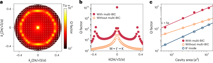
a, Two-dimensional map of the Q-factor and polarization distributions of the flat-band with multi-BIC states in momentum space. The colour map represents the Q factor and the white dashed line represents the polarization vector. The topological charge was determined to be q = +2 by selecting a circle centred around the Γ point with |k| = 0.1(2π/√3/a) (Methods). b, Q-factor comparison of the flat-band cavities with and without the multi-BIC. The simulations here are conducted with periodic boundary conditions along the x–y axis (that is, infinite cavity sizes). c, Calculated Q factors for the fundamental mode of the flat-band cavities with and without the multi-BIC, along with the cavity with normal C6v-BIC. Here the calculations are based on realistic cavity structures with finite sizes, incorporating a double-metal device configuration with the consideration of the corresponding cavity losses. The solid lines are guides for the eyes.
Measurements of flat-band multi-BIC lasers
Benefiting from the exceptional in-plane and out-of-plane field confinements offered by the flat-band multi-BIC mode as discussed, we successfully fabricated compact QCL devices with high performance. As presented in Fig. 4a,b, the lateral size of the L = 5a cavity is just 294 μm (~3λ), with the daisy-like air-hole patterns imprinted onto the QCL slab. The surrounding absorption boundary (unpatterned) is experimentally realized by inserting a thin SiO2 insulation layer between the metal and QCL medium layers (Supplementary Fig. 2). The laser was characterized by using a customized setup (Methods). The light–current–voltage (L–I–V) curves (Fig. 4c) demonstrate a distinct lasing threshold of approximately 0.19 kA cm–2, attributed to the enhanced Q factor that stems from the collective effect of the flat band with a high group index and the multi-BIC with a broad high-Q region. The ultracompact device footprint as well as the low lasing threshold leads to a small pumping current (Supplementary Fig. 17), which is essential for pursuing low-power-consumption, low-thermal-generation THz QCLs. Moreover, distinct single-mode lasing emission can be identified across the entire dynamic range (Fig. 4d,e). The single-mode performance is evaluated by calculating the SMSR of the device at a pumping current density of 0.27 kA cm–2, where the SMSR can reach up to ~20 dB (Fig. 4f). It is worth highlighting that, to the best of our knowledge, this flat-band multi-BIC QCL represents the most compact single-mode photonic-crystal laser. Additionally, the substantial group-index contrast between the E1 band and the adjacent B (E2) band effectively increases the imaginary free spectral range, thereby facilitating single-mode operation in larger cavities. We conducted full-wave simulations to assess the mode distribution and Q factor for cavities with side lengths of L = 9a and L = 17a. In both cases, the electric fields are tightly confined within the cavities with Q factors of approximately 1.0 × 10⁴ and 5.7 × 10⁴, respectively (Supplementary Fig. 18). Experimentally, stable single-mode lasing emission is maintained when continuously increasing the pumping current densities (Fig. 4h,k), with a measured SMSR of ~23 dB and ~25 dB, respectively (Fig. 4i,l).
Fig. 4: Experimental demonstration of the flat-band multi-BIC lasers.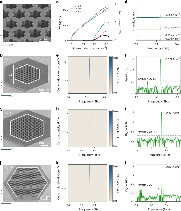
a, Zoomed-in scanning electron microscopy image of the daisy-like air-hole photonic cavity. b, Scanning electron microscopy image of the fully fabricated laser device, incorporating the cavity structure displayed in a. c, L–I–V curves of the fabricated lasers. d, Laser spectra of the L = 5a device at various pumping current densities. e, Two-dimensional spectral mapping of the L = 5a laser as a function of the frequency and pumping current density. f, Laser spectrum of the L = 5a device at 0.27 kA cm–2 with a measured SMSR of ~20 dB. g–i, Scanning electron microscopy image (g), two-dimensional spectral mapping (h) and SMSR calculation (i) of the L = 9a device. j–l, Scanning electron microscopy image (j), two-dimensional spectral mapping (k) and SMSR calculation (l) of the L = 17a device.
The far-field pattern of the designed flat-band multi-BIC laser was collected using a customized intensity scanner equipped with a THz Golay cell detector. Due to the sensitivity limitations of the detector, the L = 9a device with a peak power of 1.02 mW was characterized here (Supplementary Fig. 19). Numerical calculations indicate that the cavity mode features a cylindrical vector beam profile with good directionality and a doughnut-shaped far-field pattern (Supplementary Fig. 20a). The experimentally obtained near-C6-symmetric intensity profiles (Supplementary Fig. 20b,c) are in good agreement with the simulation results, and the beam divergence is approximately 15°.
We also fabricated control devices using an optimized photonic-bandgap-confined ‘normal C4v-BIC’ design (B″ mode) based on the same QCL wafer (Supplementary Fig. 22a–f). In particular, the observed Q factor is significantly lower (~265) than the flat-band multi-BIC mode, resulting in an enhanced lasing threshold of ~0.28 kA cm–2, despite the fact that the overall side length is larger (~5λ). Moreover, the device based on the ‘normal C4v-BIC’ design, without any optimization, can only operate with multiple modes (Supplementary Fig. 22g–i). Therefore, we emphasize that the multi-BIC-assisted flat-band cavity undoubtedly provides threshold reduction and well-preserved single-mode performance, which is not limited to THz QCLs but can be extended to any other photonic-cavity-based laser devices.