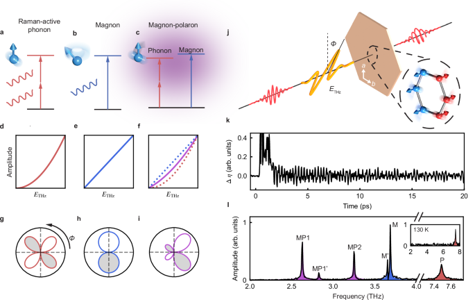
In our experiment, we measure the MPs by tracking the polarization state of an ultrashort, 800 nm probe pulse that passes through the sample. By controlling the relative delay Δt between the probe pulse and the THz excitation, the MPs appear as coherent oscillations in the probe pulse ellipticity (Δη). Figure 1k shows a typical Δη transient measured in FePS3 at 10 K as a function of Δt. The initial positive signal close to Δt = 0 arises from the THz Kerr effect when pump and probe temporally overlap. A beating pattern emerges at later delays, which indicates the coexistence of multiple coherent oscillations. A fast Fourier transform (FFT) of the time trace in Fig. 1k reveals a series of peaks corresponding to various low-energy excitations of the system (Fig. 1l). Here, the three lowest energy modes (violet shadings) and the two modes around 3.7 THz (blue shadings) disappear above the magnetic transition temperature (inset of Fig. 1l). They have been shown to result from the hybridization between phonons and magnons44,45,46,47. Therefore, they should be referred to as MPs rather than pure phonons or magnons. We label the bare phonons involved in the hybridization as P1, P1’, and P2, and the bare magnons as bare-M’, and bare-M. Due to hybridization, these modes (P1, P1’, P2, bare-M’, and bare-M) no longer represent the elementary excitations of the system. Instead, we only detect the hybridized modes MP1 (2.7 THz), MP1’ (2.8 THz), MP2 (3.3 THz), M’ (3.7 THz), and M (3.7 THz). Since the coupling strength under zero magnetic field is significantly smaller than the frequency differences between the magnons (bare-M’ and bare-M) and the phonons (P1, P1’, and P2)44, the hybridization has negligible effects on the mode frequencies. Therefore we have \({f}_{{{{{\rm{P}}}}}_{{{{\rm{i}}}}}}\approx {f}_{{{{{\rm{MP}}}}}_{{{{\rm{i}}}}}}\) for \({{{{\rm{P}}}}}_{{{{\rm{i}}}}}={{{{\rm{P1}}}}},{{{{\rm{P1}}}}}^{{\prime} },{{{\rm{P2}}}}\) and \({f}_{{{{\rm{bare}}}}-{{{{\rm{M}}}}}^{{\prime} }}\approx {f}_{{{{{\rm{M}}}}}^{{\prime} }}\), \({f}_{{{{\rm{bare}}}}-{{{\rm{M}}}}}\approx {f}_{{{{\rm{M}}}}}\). The modes MP1, MP1’, and MP2 predominantly exhibit phonon characteristics, while M’ and M are primarily magnon-like (Supplementary Note 10).
To gain insight into the symmetry and the excitation mechanisms of these modes, we investigate their amplitudes as a function of THz polarization ϕ49,50. We rotate the THz polarization ϕ while keeping ETHz, the probe polarization, and the sample orientation unchanged. Mode amplitudes are determined by integrating the area under their respective FFT peaks or by fitting to damped harmonic oscillators (Supplementary Note 3). The excitation spectrum of the modes at different ϕ are shown by the color plot in Fig. 2. Here we focus on four modes: the 2.7 THz mode (MP1), 3.3 THz mode (MP2), the mode with higher frequency around 3.7 THz (M), and the 7.5 THz mode (P). Further details regarding the remaining modes are provided in Supplementary Notes 4 and 5. We first measure the polarimetry of different modes at a low ETHz (~50 kV/cm peak electric field). Both MP1 and MP2 show distorted two-petal patterns breaking the C2 symmetry along the b-axis (Fig. 2a, b). For MP1, the two lobes are rotated towards ϕ = ± 45° (Fig. 2e), while for MP2, the left lobe is noticeably larger than the right lobe (Fig. 2f). In comparison, M shows two identical lobes (Fig. 2c, g), and P exhibits a symmetric nodeless pattern oriented along the a-axis (Fig. 2d, h). Both of M and P preserve the C2 symmetry, in contrast with the observed asymmetry in MP1 and MP2. We then repeat the polarimetry measurements at a high ETHz (~150 kV/cm peak electric field), where M and P retain their equivalent polarimetry compared to their low ETHz cases (Fig. 2k, l, o, p). On the other hand, remarkable change in the polar pattern of MPs can be observed: MP1 develops two additional lobes along ϕ = ± 135° (Fig. 2i, m), while MP2 maintains two lobes but with increased asymmetry (Fig. 2j, n).
Fig. 2: ϕ dependence of the mode amplitudes.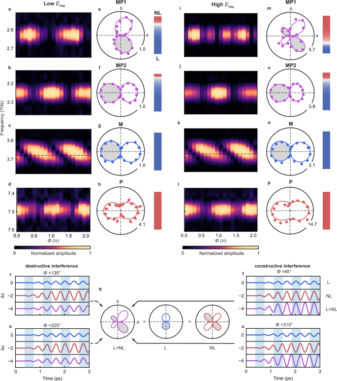
a–d FFT spectra of MP1, MP2, M, and P as a function of THz polarization ϕ at low ETHz. The amplitudes are normalized to the maximal value for each mode (see colorbar at the bottom). The horizontal dashed line at 3.68 THz marks the frequency of M. The MP1, MP2, and M modes are measured at 30% of the maximal ETHz and the P mode is measured at 50% of the maximal ETHz. ETHz = 150 kV/cm. e–h Amplitudes of MP1 (e), MP2 (f), M (g), and P (h) as a function of ϕ extracted from (a–d). Solid lines are fits. MP1 is fit by the sum of Eq. (2) and Eq. (3) for a Bg mode. MP2 is fit by the sum of Eq. (2) and Eq. (3) for a Ag mode. M is fit by Eq. (3) for a Ag mode. P is fit by Eq. (2) for a Ag mode. The white and gray shadings in the polar plots indicate opposite phases. The numbers on the polar plots represent the maximal amplitudes normalized to the maximal amplitude measured at 30% of the maximal ETHz of different modes. The color bars next to the polar plots indicate the relative strengths of the nonlinear (red) and linear (blue) pathways obtained by the fitting. i–p are identical to panels (a–h) but acquired at 100% of the maximal ETHz. The error bars show experimental standard error. q–u Schematics of the interference. q shows a typical fitting (violet) of the ϕ dependence of MP1 at highest ETHz (m), along with the linear (blue) and nonlinear (red) components of the fitting. r–u shows schematics of the MP oscillations excited by the linear channel alone (L, blue curve), the nonlinear channel alone (NL, red curve), and both linear and nonlinear channels (L+NL, violet curves). The blue shaded regions highlight different phases of the oscillations. The curves are offset for clarity.
To quantitatively understand the distinct symmetries of the polar patterns, we fit the nonlinear and linear excitation channels based on the symmetry of the the Raman phonons and the magnon, respectively. The point group 2/m allows Raman-active phonons with Ag and Bg irreducible representations (irreps). Based on the symmetry constraints, both the nonlinear and linear driving forces must share the same irrep as the corresponding phonon mode (see Supplementary Note 7). Therefore, their ϕ-dependences can be derived from the basis functions of Ag and Bg irreps in the 2/m point group (Supplementary Note 7). To this end, we expect the following ϕ-dependence of the driven amplitudes of Ag and Bg phonons from nonlinear channels:
$${A}_{{{{\rm{NL}}}},{A}_{g}}= {a}_{1}{E}_{a}^{2}+{a}_{2}{E}_{b}^{2}=({a}_{1}{\cos }^{2}\phi+{a}_{2}{\sin }^{2}\phi ){E}_{{{{\rm{THz}}}}}^{2}, \\ {A}_{{{{\rm{NL}}}}, {B}_{g}}= 2{a}_{3}{E}_{a}{E}_{b}=2{a}_{3}\cos \phi \sin \phi {E}_{{{{\rm{THz}}}}}^{2},$$
(2)
where Ea and Eb are the THz electric fields along the crystallographic a- and b-axes, respectively, and a1, a2, a3 are fitting coefficients (Supplementary Note 7). Importantly, Eq. (2) is valid for any potential quadratic nonlinear pathway, making our description universally applicable. For the linear channels, since the magnetization along a- and b-axes (Ma and Mb) respects Bg and Ag symmetry, respectively, the ϕ-dependence of the linear excitation channel of MP can be described as:
$$\begin{array}{l}{A}_{{{{\rm{L}}}},{A}_{g}}\propto {M}_{b}\propto {B}_{{{{\rm{THz}}}}}\cos \phi={b}_{1}{E}_{{{{\rm{THz}}}}}\cos \phi,\\ {A}_{{{{\rm{L}}}},{B}_{g}}\propto {M}_{a}\propto {B}_{{{{\rm{THz}}}}}\sin \phi={b}_{2}{E}_{{{{\rm{THz}}}}}\sin \phi,\end{array}$$
(3)
where BTHz is the magnetic field of the driving THz pulse, which is perpendicular to the electric field, and b1, b2 are fitting coefficients (Supplementary Note 7). The absolute value and sign of Eq. (2) and Eq. (3) represent the amplitude and phase of the oscillations induced by each pathway. The distinct angular dependence of the linear and nonlinear pathways allow for the control of their relative phase and therefore the interference. The C2 symmetry breaking behavior of MP1 and MP2 strongly suggests that they are simultaneously driven by both channels, consistent with their MP nature. We can quantitatively fit the polar patterns of MP1 and MP2 by the sum of Eq. (2) and Eq. (3) (violet lines in Fig. 2e, f, m, and n) of Bg and Ag symmetries, respectively. The mode symmetries determined here agree with assignments from polarization-dependent Raman studies51. Moreover, the pattern change of MPs at different ETHz can be explained by the alteration in the relative strengths of the nonlinear and linear pathways, which can be extracted by the ratio between the maximum fit values of the nonlinear and linear polar patterns (color bars next to each polar pattern in Fig. 2). We find that the relative strengths not only depend on ETHz but also differ between the two MPs. For MP1, the dominant excitation pathway switches from linear at low ETHz to quadratic at high ETHz. On the other hand, for MP2, the linear pathway dominates within our attainable ETHz range. While quantitative comparison between the linear excitation efficiency b1,2 of the MPs is difficult due to their different detection sensitivity, qualitatively, the large linear to nonlinear ratio of MP2 can be attributed to the small frequency difference between MP2 and M, with additional influence from the linear magnon-phonon coupling strength and nonlinear excitation coefficients (Supplementary Note 10). In comparison, M and P can be fit by considering only the linear Ag (Eq. (3)) and the quadratic Ag pathways (Eq. (2)) at all ETHz values, respectively (blue and red lines in Fig. 2g, h, o, and p). This indicates that the hybridization has negligible effects on the excitation of M, allowing it to be treated as almost a pure Ag magnon, and P is an Ag phonon that does not significantly hybridize with the magnons. Therefore, our method not only reveals and controls the nonlinear and linear excitation pathways, but also identifies the nature of the modes and determine their symmetries, without requiring an external magnetic field.
The agreement between Eqs. (2), (3) and the experiments unambiguously points out that the polar patterns of MP1 and MP2 arise from interference between the linear and nonlinear pathway. A schematics of this interference for MP1 at high ETHz (Fig. 2i and m) is provided in Fig. 2q–u for demonstration. At ϕ = 45° (Fig. 2t), the linear (blue curve) and nonlinear pathways (red curve) are in phase, resulting in constructive interference (violet curve). Rotating the THz polarization by 180° to ϕ = 225° causes the linear channel to experience a π phase shift (Eq. (3)), while the phase of the nonlinear channel remains unaffected (Eq. (2)). Consequently, destructive interference occurs, exhibiting smaller amplitude compared to the constructive interference at ϕ = 45°.
The phase of the interference pattern of MP1 (violet curves) remains unchanged for ϕ = 45° and ϕ = 225° due to the dominance of the nonlinear channel. However, when the THz polarization moves to around ϕ = 135° and ϕ = 315°, the nonlinear channel undergoes a π-phase shift, causing the interference pattern to flip phase (violet curves). In this case, constructive interference occurs around ϕ = 315°, while destructive interference is observed at ϕ = 135°.
To corroborate our interpretations and directly demonstrate the existence of both linear and nonlinear pathways, we measure the ETHz dependencies of mode amplitudes at characteristic ϕ values where the linear and nonlinear responses should be nearly maximal based on the polarimetry analysis. The amplitudes of MP1 and MP2 exhibit both linear and nonlinear behaviors depending on ϕ. Specifically, at ϕ = 92°, which is around the maximum of the linear channel (Eq. (3)) and the node of the nonlinear channel for Bg (Eq. (2)), the amplitude of MP1 shows nearly linear dependence on ETHz (Fig. 3a dotted blue line). The ETHz dependence becomes almost quadratic when we rotate the THz polarization to ϕ = 52°, close to the maxima of the nonlinear channel (Fig. 3b dotted red line). For MP2, the linear and quadratic dependence on ETHz appear at ϕ = 12° (Fig. 3c) and ϕ = 92° (Fig. 3d), respectively, distinct from MP1. The ETHz-dependencies of the MP amplitudes can all be quantitatively captured by Eq. (1). This combined linear and quadratic ETHz-dependencies at distinct ϕ values confirm the coexistence of the two pathways. In contrast, such strong ϕ dependence is not observed for M and P. At all selected ϕ values, the amplitude of M is linear in ETHz (Fig. 3e), validating the magnetic-dipole excitation pathway. Similarly, the amplitude of P consistently shows a quadratic ETHz-dependence (Fig. 3f), as expected for the sum-frequency excitation of a Raman-active phonon mode.
Fig. 3: ETHz dependence of the mode amplitudes.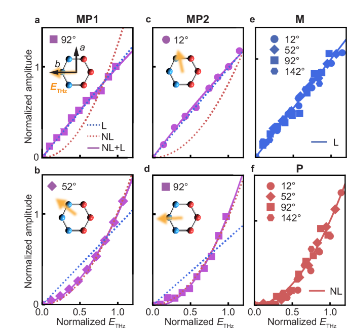
a, b MP1 amplitude as a function of ETHz obtained at ϕ = 92° and ϕ = 52°, respectively. c, d, MP2 amplitude as a function of ETHz obtained at ϕ = 12° and ϕ = 92°, respectively. e M amplitude as a function of ETHz at different ϕ values. Data are normalized for a better comparison. f P amplitude as a function of ETHz at different ϕ values. Data are normalized for better comparison. In all the panels, red and blue lines are quadratic and linear fits, while violet lines are the fits to Eq. (1). The insets show the THz polarization with respect to the crystallographic axes. ETHz is normalized by 180 kV/cm. The chosen ϕ values are not perfectly aligned with the crystallographic axes due to difficulties in sample alignment.
The combined measurements of ϕ and ETHz dependencies of the MP1 and MP2 amplitudes substantiate the coexistence of linear and nonlinear pathways and their interference. To further corroborate the symmetry of different MPs, we fit the ETHz-dependence of MP amplitudes using Eq. (1) systematically at various ϕ values. We thereby obtain the ϕ-dependence of parameters a and b of Eq. (1), which directly reflect the symmetry of the nonlinear and linear excitation channels. Notably, a(ϕ) of MP1 exhibits four equal petals, each offset by 45° from the crystallographic axes (Fig. 4a), suggesting the Bg-symmetry as we previously assigned. Conversely, a(ϕ) of MP2 shows four petals aligned with the crystallographic axes (Fig. 4b), in agreement with the expected Ag-symmetry. Similarly, b(ϕ) of MP1 and MP2 exhibit two equal lobes aligned with the b- and a-axes (Fig. 4c and d), respectively, consistent with the assignment of Bg- and Ag-symmetry as predicted by Eq. (3). Hence, the coexistence of both nonlinear and linear channels yields either constructive (a(ϕ)b(ϕ) > 0, see the shadings of Fig. 4a–d) or destructive (a(ϕ)b(ϕ) ϕ, giving rise to the ostensible C2-symmetry breaking.
Fig. 4: Nonlinear and linear pathways for MP excitation and their applications.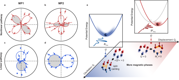
a, b Nonlinear pathway efficiency a for MP1 (a) and MP2 (b) as a function of ϕ. Red lines are fits for the Bg and Ag modes to Eq. (2). c, d Linear pathway efficiency b for MP1 (c) and MP2 (d) as a function of ϕ. Blue lines are fits for the Bg and Ag modes to Eq. (3). The white and gray shaded regions indicate different signs of the coefficients a and b, which will lead to opposite phases of MP oscillations. The error bars show the standard error of fittings. e Schematics of the dynamical phase diagram induced by coherent MPs. Red region: Mz ≠ 0 state induced by MP2 net displacement Q0. The red and blue spheres are Fe atoms with equilibrium spin up and spin down. The bonds with exchange interaction enhanced (thicker bonds) and weakened (thinner bonds) by the phonon displacement are highlighted in yellow. The red and blue arrows indicate the average spin of different Fe atoms upon THz excitation. Top inset shows the schematic of the potential energy landscape change upon driving the MP through the nonlinear displacive pathway. Blue region: spin-canting state induced by MP2 oscillation Q1. The solid yellow lines depict the new spin interaction terms (Si × Sj) ⋅ (Sk × Sl) induced by hopping between Floquet bands. Left inset shows schematic of the potential energy landscape upon driving the MP through the linear pathway, where the phonon oscillates symmetrically around the equilibrium position. White region: more magnetic phases induced by different relative strength between Q0 and Q1.
To substantiate our phenomenological descriptions and quantitatively understand the experimental observations, we perform microscopic dynamical simulations (Methods). We start by constructing an equilibrium Hamiltonian describing the spin degree of freedom which includes magnetic exchange interactions and anisotropy with all the microscopic parameters determined by first-principles calculations. We then derive the spin dynamics by solving the Landau-Lifshitz-Gilbert (LLG) equation based on the Hamiltonian with a time-dependent magnetic driving field. This allows us to obtain the dynamics of the magnon-induced magnetization M(t), which determines the nonlinear effective force TQ(t) (see Supplementary Note 6 and 8 for more discussions) and the linear effective force from the magnetic-dipole process gM(t), where g is the magnon-phonon coupling strength. The dynamics of the MP can then be simulated by its equations of motion:
$$\ddot{Q}+2{\gamma }_{Q}\dot{Q}+{\omega }_{Q}^{2}Q={T}_{Q}(t)+gM(t),$$
(4)
where Q, γQ, and ωQ are the displacement amplitude, damping rate, and frequency of the MP. By comparing the theoretical simulations with the experimental observations, we achieve a remarkable agreement in terms of the dependence on ETHz and ϕ, confirming the validity of our proposed excitation mechanisms (Supplementary Note 8).