Mechanisms of energy transfer in RF electrosurgery for thermal interaction with biological tissue
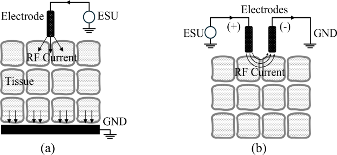
RF electrosurgery achieves tissue heating by delivering high-frequency electrical energy, typically in the range of hundreds of kilohertz to several megahertz. For surgical applications such as cutting and coagulation, frequencies in the hundreds of kilohertz are most commonly used. The system consists of an RF generator (ESU) and electrodes that establish electrical potential across tissue. RF electrodes are generally classified as monopolar or bipolar, depending on the configuration controlled by the surgeon. In bipolar systems, current flows across a confined tissue path between two electrodes. In contrast, monopolar systems deliver RF energy along a broader path, as depicted in Fig. 128, with the active electrode in contact with the tissue and the return path completed via patient grounding. As shown in Fig. 2, the monopolar electrode—constructed from conductive metal and insulating materials—delivers high-voltage RF energy from the ESU to the tissue. This energy transfer gives rise to three distinct heating mechanisms: dielectric heating through oscillating electric fields, resistive heating from conduction currents, and localized heating associated with electron avalanche effects.
Dielectric heating in RF electrosurgery occurs when polar molecules—primarily water—respond to high-frequency alternating electric fields by oscillating, generating heat through friction. As water is the primary constituent of human tissue, the polarity of water molecules (H₂O), due to differences in electron affinity between hydrogen and oxygen, makes them highly responsive to these fields. Oscillating at rates over 400,000 times per second, water molecules collide with adjacent molecules, increasing thermal motion and producing heat. This selective heating of intracellular moisture induces a temperature rise within the tissue itself rather than at the electrode–tissue interface. Moreover, the temperature elevation is inherently self-limiting due to the vaporization threshold of water at 100 °C, which prevents excessive thermal buildup. As a result, this mechanism is considered both safe and effective for cutting and coagulation, with minimized collateral damage. The amount of heat generated W is influenced by the tissue’s relative permittivity ε), dielectric loss tan δ, electric field intensity E, and frequency f, as in Eq. (1)29,30.
$$W \propto {\varepsilon _r}\cdot tan\delta\cdot f\cdot{E^2}\left[ {W/{m^3}} \right]\;\;$$
(1)
Effective dielectric heating under fixed frequency and voltage conditions requires precise optimization of electrode shape and insulation in order to intensify the local electric field. This has long presented a critical challenge in the design of monopolar electrosurgical electrodes. Ensuring that the electrode retains a high potential during contact with low-potential tissue demands the use of advanced materials and engineering approaches. These include the development of high-durability conductors and insulators, along with detailed analysis and modeling to ensure stability under high-voltage, high-temperature operating conditions.
For the reasons outlined above, the vast majority of monopolar electrodes rely on resistive heating—commonly described by the I²R or V²/R principle—to generate thermal energy in tissue. The critical factor in this mechanism is the resistance R, which is primarily governed by the contact resistance between the conductive electrode and the tissue surface. This is particularly important because the cross-sectional area of the RF current path increases significantly as current travels from the electrode–tissue interface to the patient’s grounding pad. Resistance values typically range from several hundred to several thousand ohms and vary depending on factors such as surface roughness of both the tissue and electrode, as well as tissue moisture content. Therefore, the amount of heat generated via resistive heating is determined by the total impedance of the RF path, which includes this surface-level contact resistance.
In addition to the two primary heating mechanisms described above, most monopolar electrodes are also subject to an unavoidable phenomenon known as dielectric discharging. Regardless of the heating principle employed, electrodes designed for efficient cutting typically feature thin, narrow (blade-shaped) or sharp, pointed (needle-shaped) designs. These shapes often result in dielectric breakdown of the air—or, in surgical environments, air mixed with blood and other impurities—just before making physical contact with the low-potential tissue. These air dielectric breakdown events, which occur over extremely short durations (on the microsecond level), are highly localized and random, making them almost impossible to intentionally control by the user. They have traditionally been considered an unavoidable phenomenon during RF surgery. However, certain electrosurgical unit (ESU) modes, such as those employing high-voltage pulsed waveforms, are sometimes used to intentionally increase the frequency of these breakdown events31. The accompanying electron avalanche phenomenon, which occurs simultaneously with dielectric breakdown, can cause the tissue temperature at the discharge point to rise instantaneously to several hundred to over a thousand degrees Celsius. This results in immediate tissue destruction (e.g., rupture and carbonization) and provides an associated hemostatic effect at the site.
Monopolar blade-type electrode structure for efficient dielectric heating
From bare metal to laterally insulated designs, conventional monopolar blade-type electrodes have been developed to minimize collateral thermal damage by limiting tissue contact to the cutting edge during electrosurgery. Further refinement led to the Advanced Energy Blade, incorporating a sharpened tip and advanced coatings such as glass or composite anti-adhesive materials. While this design improves precision and reduces tissue injury compared to silicone- or Teflon-coated predecessors, it still operates using conventional resistive heating. As a result, high temperatures along the blade and incision site continue to pose risks of thermal damage to surrounding tissues and implanted devices.
Figure 3 illustrates the proposed DUO monopolar blade electrode, as first introduced by the authors32,33 in Fig. 3(a) and (b), which is optimized for capacitive coupling–based dielectric heating with adjacent tissue to enhance the safety and precision of RF electrosurgery. The design aims to reduce collateral tissue damage, protect implanted devices, and minimize thermal necrosis and carbonization. As illustrated in Fig. 3(c), the proposed electrode is designed to utilize dielectric heating as the primary energy transfer mechanism for tissue dissection. The electric field emitted from the electrode selectively heats water molecules within the tissue, and this localized heating results in tissue coagulation caused by thermal denaturation, as well as cellular rupture due to vaporization-driven cutting. Once the water content in the targeted region is depleted due to vaporization, further heating naturally ceases. This built-in temperature-limiting behavior serves as a key design principle, enabling controlled and safe energy delivery during electrosurgery. The tapered geometry of the electrode, narrowing from the center toward the edge, was designed to work in conjunction with the insulated edge to enhance electric field concentration at the tip and to maximize the frequency of secondary dielectric breakdown and the resulting plasma discharges at the tissue–electrode interface. This secondary dielectric breakdown mechanism, though relatively weak in magnitude, provides a directional and supplemental pathway for energy delivery that facilitates tissue cutting. Simultaneously, the tapered shape helps to minimize mechanical friction between the electrode surface and the tissue during incision, contributing to smoother and more precise surgical performance.
Fig. 3
Proposed dielectric ultra-focused oscillatory (DUO) blade for electrosurgery: (a) Structure and the concept of capacitive coupling with tissue, (b) Blade edge and its key design variables, (c) Heating mechanism.
To achieve the aforementioned design objectives, the blade incorporates a precisely sharpened edge and a laminated dual-insulation structure composed of a metal oxide layer and PTFE. The device is fabricated by forming an anodized aluminum oxide (Al₂O₃) layer on an aluminum core—chosen for its controllable oxide thickness—and subsequently applying a PTFE spray coating on the exterior. Each layer possesses a distinct dielectric constant, and these materials are strategically arranged to concentrate the electric field at the cutting edge while simultaneously supporting hemostasis along the lateral surfaces. The thicknesses of both the blade tip and insulating layers were optimized through finite element analysis (FEA) and validated experimentally, confirming the superior thermal performance of the DUO electrode.
Optimization of electrode structure using finite element analysis and deep reinforcement learning
The structure of the proposed DUO blade was optimized to adjust the electric field distribution at a distance of 50 μm from the electrode, which is greater than the average diameter of tissue structures encountered in electrosurgery34. To achieve an appropriate balance between cutting and coagulation effects by tailoring the electric field, a deep reinforcement learning (DRL) framework integrated with finite element analysis (FEA) was employed to identify the optimal solution among a wide range of candidates35. Considering the characteristic of dielectric heating being proportional to the square of the electric field as described in Eq. (1), the optimal thicknesses of each layer—d₁, d₂, and d₃ in Fig. 3—and their combination were defined as design goals to ensure that the integrated electric field in the vertical direction (normal to the blade–tissue interface) is 30% greater than that in the horizontal direction. The DRL agent observes the current design state as a vector consisting of three thickness parameters. The electromagnetic simulation was conducted using the dielectric and conductive properties of the materials listed in Table 136. Liver tissue was selected as the bulk material for evaluation, as it is a representative soft, high–water-content tissue containing a dense vascular network, and thus exhibits electrical conductivity and permittivity characteristics representative of various biological tissues. To simulate the presence of inevitable necrotic tissue during electrosurgery, a 5 μm-thick layer of dry tissue was assumed to surround the blade in the analysis model. Each layer in Fig. 3(a) was selected based on their distinct electrical and thermal properties, with aluminum serving as a conductive core, metal oxide as a high-permittivity dielectric, and PTFE as an insulator with anti-adhesive characteristics as in Table 1. The averaged integrated electric field intensities between intervals of α and β in Fig. 4 were monitored, and various combinations of the critical design variables were explored and optimized using the proposed deep reinforcement learning framework, as illustrated in Fig. 5.
Table 1 Material properties used in the blade design.Fig. 4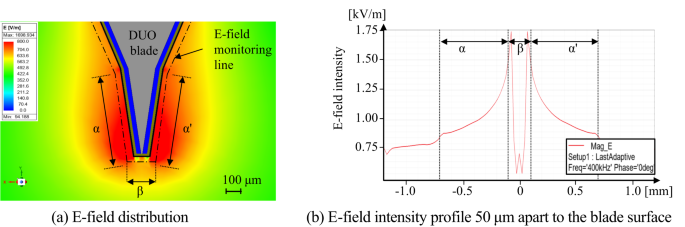
FEM analysis results result when 400 kHz 100 V sinusoidal voltage is applied for the proposed DUO blade.
Fig. 5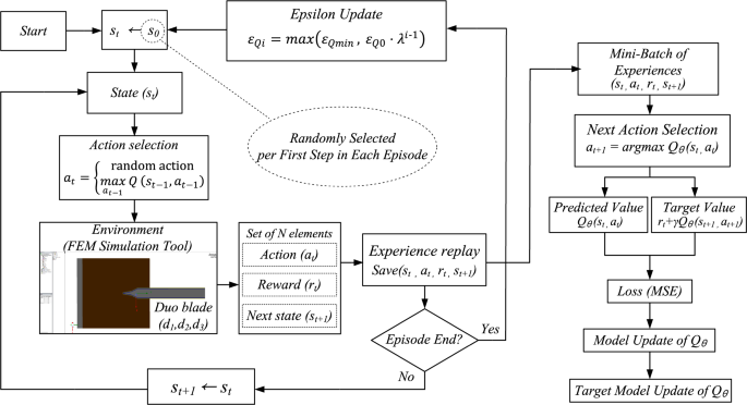
Operational mechanism of the proposed DRL algorithms.
The optimization was guided by a Deep Q-Network (DQN) algorithm37. Each combination of (d1, d2, d3) represented a state, and possible actions included increasing, decreasing, or maintaining each parameter. Learning proceeded over episodes consisting of 50 steps, following an ε-greedy policy38. Initially, the agent fully explored the action space (εQ=1.0) and gradually shifted toward exploitation as εQ decayed with each episode. The overall structure of the proposed DRL-based optimization procedure is illustrated in Fig. 5, and the appropriate hyperparameters for the proposed DRL is summarized in Table 23940. These hyperparameters were selected to ensure a stable learning process and efficient convergence. The discount factor γ balances immediate and future rewards, while a small learning rate α provides gradual updates to avoid oscillations. An exponentially decaying exploration rate λ enables a smooth transition from exploration to exploitation. The replay buffer size and batch size were chosen to ensure training stability and sufficient sample diversity. The network architecture (3-32-32-7) reflects the dimensionality of the state and action spaces and provides sufficient capacity for policy approximation. The DRL agent observes the current design state as a vector consisting of three thickness parameters as shown in Eq. (2):
Table 2 Hyperparameter selection for the proposed deep reinforcement learning.
$$\:{s}_{t}=\left[\begin{array}{c}{d}_{1}\left(t\right)\\\:{d}_{2}\left(t\right)\\\:{d}_{3}\left(t\right)\end{array}\right]$$
(2)
Modifying multiple design parameters simultaneously leads to an exponential increase in the design space, which destabilizes the training process. Accordingly, the action space at ∈ ℝ3 is constrained such that only one component is modified, or all components remain unchanged at each step. Thus, at every step, either one of the parameters d1, d2, or d3 is adjusted by ± Δ or no change occurs. This results in a total of 7 possible discrete actions, as in Eqs. (3) and (4).
$$\:\mathcal{A}=\left\{\left[\begin{array}{c}\pm\:5\\\:0\\\:0\end{array}\right],\left[\begin{array}{c}0\\\:\pm\:10\\\:0\end{array}\right],\left[\begin{array}{c}0\\\:0\\\:\pm\:5\end{array}\right],\left[\begin{array}{c}0\\\:0\\\:0\end{array}\right]\right\}$$
(3)
.
$$\:{s}_{t+1}={s}_{t}+{\Delta\:}{a}_{t}\:,\:\:\:\:where{\:a}_{t}\in\:\mathcal{A}$$
(4)
After each action, the FEA simulation yielded an updated electric field distribution. A scalar reward was then computed based on how closely this distribution aligned with a predefined optimal energy pattern between the blade’s edge and side regions, as illustrated in Fig. 4(b). The reward formulation is given in Eq. (5) which evaluates how effectively the electric field remains within a desired intensity range across the specified region.
$$\:R\left({d}_{1},{d}_{2},{d}_{3}\right)=\frac{1}{{x}_{max}-{x}_{min}}{\int\:}_{{x}_{min}}^{{x}_{max}}I\left({E}_{min}\le\:E\left(x\right)\le\:{E}_{max}\right)dx\:\:\:\:\:\:\:\:\:\:\:\:\:\:\:\:\:\:\:\:\:\:\:\:\:\:\:\:\:\:\:\:\:\:\:\:\:\:\:\:\:\:\:\:\:\:\:\:\left(5\right)$$
The experiences were stored in a replay buffer and used for mini-batch training of the Q-network. The Q-values were updated using the Bellman Eq. 38 which defines the target value yt for each state-action pair as in Eq. (5), where each episode i ≥ 1 consisted of 50 simulation steps t ∈ {1,2,…,50}.
$$\:{y}_{t}={r}_{t}+\gamma\:\underset{{a}_{t+1}}{{max}}{Q}_{{\theta\:}^{-}}\left({s}_{t+1},{a}_{t+1}\right)$$
(5)
In Eq. (5), γ∈[0,1] is the discount factor, Qθ- is the target Q-network with parameters θ−, and st+1, at+1 are the next state and action, respectively. The loss function was defined as the mean squared error between the predicted and target Q-values, and the network weights were optimized using gradient descent. The loss is computed as in Eq. (7)3738.
$$\:\mathcal{L}\left({\uptheta\:}\right)={E}_{\left({s}_{t},{a}_{t},{r}_{t},{s}_{t+1}\right)}\left[{\left({y}_{t}-{Q}_{{\uptheta\:}}\left({s}_{t},{a}_{t}\right)\right)}^{2}\right]$$
(6)
To ensure stability, the target network was periodically synchronized with the main Q-network, allowing the agent to gradually converge to an optimal combination of structural thicknesses through the iterative learning process. The progression of this process is illustrated in Fig. 6, which presents representative results from episodes 1 and 200, showing the evolution of action selection and parameter tuning, while the intermediate results from episodes 30 and 120, demonstrating gradual convergence, are provided in Supplementary Fig. S1. In each episode, the agent selected an action from a discrete space consisting of increase, decrease, or maintain operations for each design parameter d1, d2, and d3. The top panels of Fig. 6 show the probability distribution for each action, while the bottom panels show the corresponding parameter values and the resulting electric field ratio between the edge and side. The action selection policy follows an ε-greedy rule as in Eq. (7).
$$\:{a}_{t}=\left\{\begin{array}{cc}\text{random action}&\,\text{with probability}\text{}{\epsilon\:}_{Qi}\\\:\:\:\:{arg}\underset{a}{{max}}Q\left({s}_{t},a\right)&\:\text{}\text{with probability}\text{}\,1-{\epsilon\:}_{Qi}\end{array}\right.$$
(7)
Fig. 6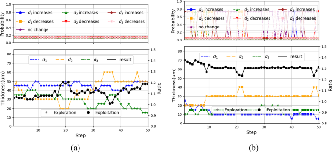
Progression of the proposed DRL: (a) Episode 1: initial exploration phase, (b) Episode 200: Convergence to optimal design parameters.
The ε-value decays over time, as in Eq. (8), ensuring a gradual transition from exploration to exploitation by exponentially reducing the exploration rate until it reaches a predefined minimum threshold \(\:{{\upepsilon\:}}_{Qmin}\).
$$\:{{\upepsilon\:}}_{Qi}=\text{max}\left({{\upepsilon\:}}_{Qmin},\:{{\upepsilon\:}}_{Q0}\cdot\:{{\uplambda\:}}^{i-1}\right)$$
(8)
Initially, in episode 1, the exploration rate εQ0 in Eq. (8) was set to 1.0, resulting in fully random behavior. As training progressed and εQ decayed, the agent increasingly favored high-reward actions. By episode 30, exploitation behavior had begun to dominate. Episode 120 marked a transitional phase where the agent refined its selections, and by episode 200, the electric field distribution progressively aligned with the desired energy localization pattern, confirming the agent’s ability to converge toward an optimal design. The corresponding optimal layer thicknesses were determined to be 10 μm for d₁, 30 μm for d₂, and 20 μm for d₃. The final design achieved an electric field ratio of 1.305 between the blade edge β and lateral surface α, corresponding to the highest reward observed during training, thereby verifying the efficacy of the DRL-guided optimization process.